30-second summary
Voltmeter
Voltmeters are instruments used for measuring the electric potential difference between two points in an electric circuit. To find the potential difference between any two points in the circuit, the voltmeter terminals are connected between those points without breaking or cutting the wire.
ΔV = Va – Vb
The most common types of voltmeters are:

Voltmeters are instruments used for measuring the electric potential difference between two points in an electric circuit. To find the potential difference between any two points in the circuit, the voltmeter terminals are connected between those points without breaking or cutting the wire. Voltmeters are connected in parallel. They are made in a wide range of styles, some separately powered (e.g. by the battery), and others powered by the measured voltage source itself. Their functionality is usually built into modern multimeters.
An ideal voltmeter would have infinite resistance, so connecting it between two points in a circuit would not alter any of the currents. Real voltmeters always have finite resistance, but a voltmeter should have large enough resistance that connecting it to a circuit does not change the other currents appreciably. Voltmeters that can measure a potential difference of 1 μV are common, and sensitivities down to 10-12 can be attained. Digital meters can be made with high accuracy, typically better than 1%. Specially calibrated test instruments have higher accuracies.
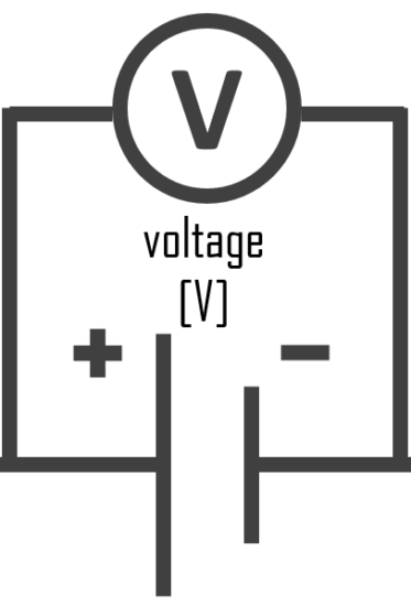
Voltmeter – Symbol of Voltmeter
In circuit diagrams, a voltmeter is represented by the letter V in a circle, with two emerging lines representing the two points of measurement.
Characteristics
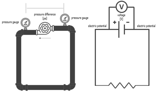
Voltmeter and Hydraulic Analogy
The hydraulic analogy, or the electric-fluid analogy, is a widely used analogy between hydraulics and electricity, which is a useful tool for teaching and for those who are struggling to understand how circuits work. it can also be applied to heat transfer problems.
Since electric current is invisible and the processes in play in electronics are often difficult to demonstrate, the various electronic components are represented by hydraulic equivalents. The relationship between voltage and current is defined (in ohmic devices like resistors) by Ohm’s law. Ohm’s Law is analogous to the Hagen–Poiseuille equation, as both are linear models relating flux and potential in their respective systems.
Electricity (as well as heat) was originally understood to be a kind of fluid, and the names of certain electric quantities (such as current) are derived from hydraulic equivalents.
Voltage is like the pressure difference that pushes water through the hose. It is measured in volts (V). This model assumes that the water is flowing horizontally so that the force of gravity can be ignored. So that voltmeter is equivalent to pressure difference measurement.
How does a voltmeter work?
A common analog voltmeter, for example, is likely to use an electromechanical mechanism that converts current flowing through the wire into a voltage reading. An analog voltmeter usually contains a built-in, high-value fixed resistance, and an ammeter measuring the current passing through it. The current sensed by the ammeter is then converted to reading in volts. Its operation is based on Ohm’s law idea: “Voltage across a resistance is directly proportional to the current traveling through it,”.
Ohm’s law: V = I x R
For example, the D’Arsonval meter or galvanometer works by deflecting a pointer in response to an electric current flowing through a coil in a constant magnetic field. A moving coil galvanometer can be used as a voltmeter by inserting a resistor in series with the instrument. The galvanometer has a coil of fine wire suspended in a strong magnetic field. When an electric current is applied, the interaction of the magnetic field of the coil and of the stationary magnet creates a torque, tending to make the coil rotate. The torque is proportional to the current through the coil. The coil rotates, compressing a spring that opposes the rotation. The deflection of the coil is thus proportional to the current, which in turn is proportional to the applied voltage, which is indicated by a pointer on a scale.
Types of Voltmeters
The different types of voltmeters are determined by the construction principle and measurement types, which are:
- Permanent Magnet Moving Coil Voltmeter – PMMC
- Moving Iron Voltmeter
- Digital Voltmeter – DVM
- Electrodynamometer
- Rectifier Type Voltmeter
- Induction Type Voltmeter
- Electrostatic Type Voltmeter
Applications of Voltmeter
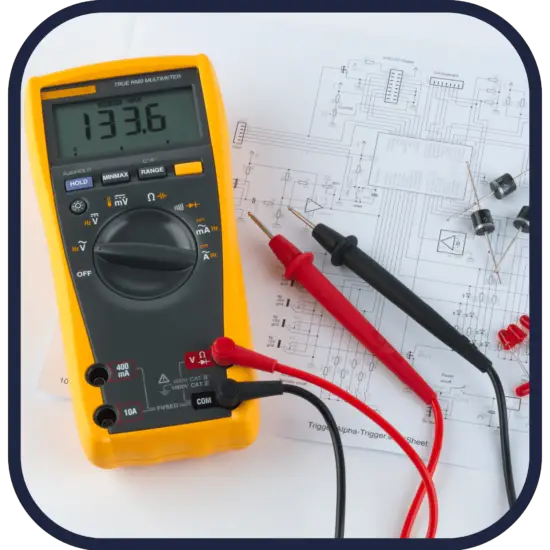
You can measure the voltage of household circuitry or batteries using a digital multimeter, an analog multimeter, or a voltmeter. Most electricians and novices prefer a digital multimeter, but you can also use an analog multimeter.
Voltage measurement is important in conjunction with all types of power supplies, to verify their performance. Instruments permanently mounted in a panel are used to monitor generators or other fixed apparatus. A voltmeter may also be used to show the output from various types of analog sensors that have voltage output. A graphical display may be used in audio equipment to indicate signal level, which can be proportional to voltage.
Analog and Digital Voltmeter
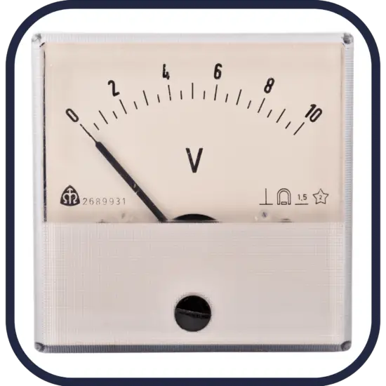
Many voltmeters are digital, with numerical displays for readings. The voltmeter instruments also offer analog readings by moving a pointer on a scale to indicate voltage; however, digital voltmeters are generally more accurate than analog instruments. An analog panel meter is shown in the figure. The different scales on the dial correspond with separate input terminals at the rear of the unit. Modern analog voltmeters are still manufactured and may be cheaper than their digital equivalents. Digital voltmeters give a numerical display of voltage by use of an analog-to-digital converter. However, a digital volt meter allows a wider range of values to be viewed more easily.
Difference Between DC and AC Voltmeter
The DC voltmeter is used to measure DC voltage, whereas the AC voltmeter is used to measure AC voltage. The peak value of DC voltage is measured by the DC voltmeter, whereas the RMS value of AC voltage is measured by the AC voltmeter. A rectifier is not used before a multistage amplifier in a DC voltmeter, but an AC voltmeter measures the RMS value of the AC voltage.
Typical voltages
To help compare different orders of magnitude, the following list describes typical voltage levels.
- 1.5V (DC) – A common open circuit voltage for non-rechargeable alkaline batteries (e.g. AAA, AA, and C cells).
- 3.8V (DC) – Almost all smartphone batteries work at 3.8 volts. In order to make current flow from the charger to the battery, there must be a potential difference. Therefore battery chargers or USBs for almost all smartphones provide a voltage of 5V.
- 12V (DC) – A common voltage for automobile batteries is 12 volts (DC).
- 110 – 120V (AC) – The most common electrical outlet in any home. The American continent uses a voltage of 110 to 120 volts (AC) while Europe, Asia, and Africa use 220 to 240 volts (AC).
- 3kV – Voltage required to generate every 1mm of an electric arc. Air is a very bad conductor of electricity and has high dielectric strength. The dielectric strength of air is nearly 3000V/mm.
- 110kV – The voltage in electric power transmission lines used to distribute electricity from power stations can be several hundred times greater than consumer voltages, typically 110 to >500 kV (AC).
- 300 MV – A typical lightning flash is about 300 million Volts and about 30,000 Amps.

Frequently asked questions
You can measure the voltage of household circuitry or batteries using a digital multimeter, an analog multimeter, or a voltmeter. Most electricians and novices prefer a digital multimeter, but you can also use an analog multimeter.
An ideal voltmeter would have infinite resistance, so connecting it between two points in a circuit would not alter any of the currents. Real voltmeters always have finite resistance, but a voltmeter should have large enough resistance that connecting it to a circuit does not change the other currents appreciably.
Most common types of voltmeters are: Permanent Magnet Moving Coil Voltmeter – PMMC, Moving Iron Voltmeter, Digital Voltmeter – DVM, Electrodynamometer, Rectifier Type Voltmeter, Induction Type Voltmeter, and Electrostatic Type Voltmeter.
