30-second summary
PMMC Voltmeter
Permanent Magnet Moving Coil Voltmeter – PMMC is also known as the D’Arsonval meter or galvanometer, and it is used to determine the angular deflection in a uniform magnetic field to determine the current flowing through the coil.
The PMMC instrument cannot be used on AC currents or voltages. If an AC supply is given to these instruments, an alternating torque will be developed. On the other hand, the cost of these instruments is higher than that of moving iron instruments.
Other types of voltmeters are:

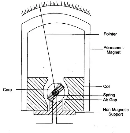
Permanent Magnet Moving Coil Voltmeter – PMMC is also known as the D’Arsonval meter or galvanometer, and it is used to determine the angular deflection in a uniform magnetic field to determine the current flowing through the coil. A PMMC meter places a coil of wire (i.e. a conductor) in between two permanent magnets in order to create a stationary magnetic field. According to Faraday’s Laws of electromagnetic induction, a current carrying conductor placed in a magnetic field will experience a force in the direction determined by Fleming’s left-hand rule. It has the benefits of a linear scale, low power consumption, and great precision. The permanent magnet moving coil instrument is the most accurate type for DC measurements. The PMMC instrument cannot be used on AC currents or voltages. If an AC supply is given to these instruments, an alternating torque will be developed. On the other hand, the cost of these instruments is higher than that of moving iron instruments.
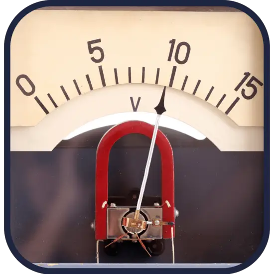
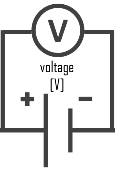
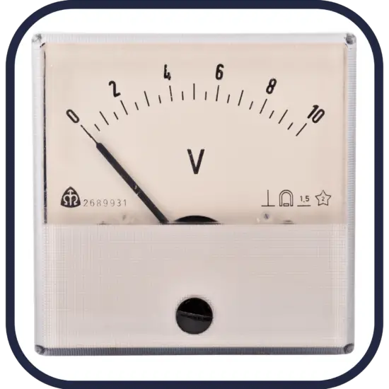
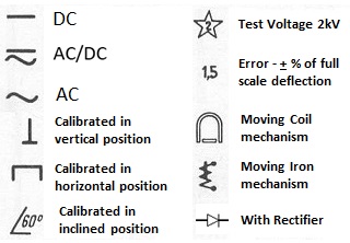
Voltmeter – Symbol of Voltmeter
In circuit diagrams, a voltmeter is represented by the letter V in a circle, with two emerging lines representing the two points of measurement.
Characteristics
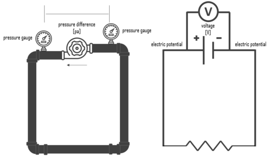
Voltmeter and Hydraulic Analogy
The hydraulic analogy, or the electric-fluid analogy, is a widely used analogy between hydraulics and electricity, which is a useful tool for teaching and for those who are struggling to understand how circuits work. it can also be applied to heat transfer problems.
Since electric current is invisible and the processes in play in electronics are often difficult to demonstrate, the various electronic components are represented by hydraulic equivalents. The relationship between voltage and current is defined (in ohmic devices like resistors) by Ohm’s law. Ohm’s Law is analogous to the Hagen–Poiseuille equation, as both are linear models relating flux and potential in their respective systems.
Electricity (as well as heat) was originally understood to be a kind of fluid, and the names of certain electric quantities (such as current) are derived from hydraulic equivalents.
Voltage is like the pressure difference that pushes water through the hose. It is measured in volts (V). This model assumes that the water is flowing horizontally so that the force of gravity can be ignored. So that voltmeter is equivalent to pressure difference measurement.