30-second summary
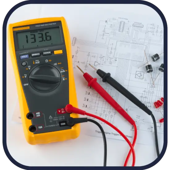
Digital Voltmeter
Digital voltmeters are voltmeters that display AC and DC voltage values and use discrete numbers instead of pointer deflection, they are preferred over analog voltmeters. DVMs are usually designed around a special type of analog-to-digital converter called an integrating converter.
Other types of voltmeters are:

Digital voltmeters are voltmeters that display AC and DC voltage values and use discrete numbers instead of pointer deflection, they are preferred over analog voltmeters. DVMs are usually designed around a special type of analog-to-digital converter called an integrating converter. An integrating ADC is a type of analog-to-digital converter that converts an unknown input voltage into a digital representation through the use of an integrator. In its basic implementation, the dual-slope converter, the unknown input voltage is applied to the input of the integrator and allowed to ramp for a fixed time period (the run-up period). Then a known reference voltage of opposite polarity is applied to the integrator and is allowed to ramp until the integrator output returns to zero (the run-down period). The input voltage is computed as a function of the reference voltage, the constant run-up time period, and the measured run-down time period. The run-down time measurement is usually made in units of the converter’s clock, so longer integration times allow for higher resolutions. Converters of this type (or variations on the concept) are used in most digital voltmeters for their linearity and flexibility.
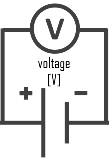
Voltmeter – Symbol of Voltmeter
In circuit diagrams, a voltmeter is represented by the letter V in a circle, with two emerging lines representing the two points of measurement.
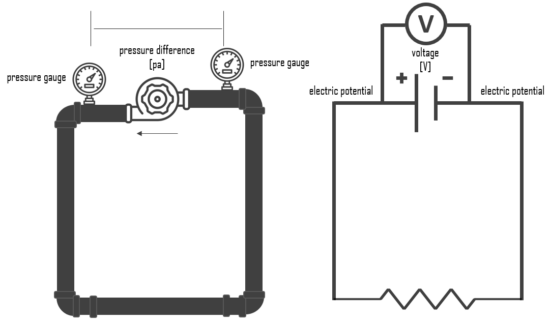
Voltmeter and Hydraulic Analogy
The hydraulic analogy, or the electric-fluid analogy, is a widely used analogy between hydraulics and electricity, which is a useful tool for teaching and for those who are struggling to understand how circuits work. it can also be applied to heat transfer problems.
Since electric current is invisible and the processes in play in electronics are often difficult to demonstrate, the various electronic components are represented by hydraulic equivalents. The relationship between voltage and current is defined (in ohmic devices like resistors) by Ohm’s law. Ohm’s Law is analogous to the Hagen–Poiseuille equation, as both are linear models relating flux and potential in their respective systems.
Electricity (as well as heat) was originally understood to be a kind of fluid, and the names of certain electric quantities (such as current) are derived from hydraulic equivalents.
Voltage is like the pressure difference that pushes water through the hose. It is measured in volts (V). This model assumes that the water is flowing horizontally so that the force of gravity can be ignored. So that voltmeter is equivalent to pressure difference measurement.