30-second summary
Voltage Measurement
In physics, voltage is the difference in electric potential between two points. Voltage, denoted by V, is defined as the amount of work energy needed to move a unit of electric charge from a reference point (a) to a specific point (b) in an electric field.
ΔV = Va – Vb
Although the concept of electric potential is useful in understanding electrical phenomena, only differences in potential energy are measurable. These differences in potential energy are measured with a voltmeter. Often a common reference potential such as the ground of the system is used as one of the points. A voltage can represent either a source of energy or the loss, dissipation, or storage of energy.
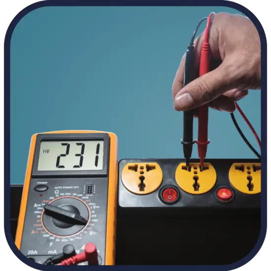

Voltmeters are instruments used for measuring the electric potential difference between two points in an electric circuit. To find the potential difference between any two points in the circuit, the voltmeter terminals are connected between those points without breaking or cutting the wire. Voltmeters are connected in parallel. They are made in a wide range of styles, some separately powered (e.g. by the battery), and others powered by the measured voltage source itself. Their functionality is usually built into modern multimeters.
An ideal voltmeter would have infinite resistance, so connecting it between two points in a circuit would not alter any of the currents. Real voltmeters always have finite resistance, but a voltmeter should have large enough resistance that connecting it to a circuit does not change the other currents appreciably. Voltmeters that can measure a potential difference of 1 μV are common, and sensitivities down to 10-12 can be attained. Digital meters can be made with high accuracy, typically better than 1%. Specially calibrated test instruments have higher accuracies.
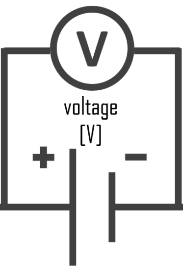
Voltmeter – Symbol of Voltmeter
In circuit diagrams, a voltmeter is represented by the letter V in a circle, with two emerging lines representing the two points of measurement.
Voltmeter and Hydraulic Analogy
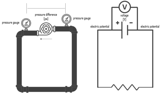
The hydraulic analogy, or the electric-fluid analogy, is a widely used analogy between hydraulics and electricity, which is a useful tool for teaching and for those who are struggling to understand how circuits work. it can also be applied to heat transfer problems.
Since electric current is invisible and the processes in play in electronics are often difficult to demonstrate, the various electronic components are represented by hydraulic equivalents. The relationship between voltage and current is defined (in ohmic devices like resistors) by Ohm’s law. Ohm’s Law is analogous to the Hagen–Poiseuille equation, as both are linear models relating flux and potential in their respective systems.
Electricity (as well as heat) was originally understood to be a kind of fluid, and the names of certain electric quantities (such as current) are derived from hydraulic equivalents.
Voltage is like the pressure difference that pushes water through the hose. It is measured in volts (V). This model assumes that the water is flowing horizontally so that the force of gravity can be ignored. So that voltmeter is equivalent to pressure difference measurement.
Types of Voltmeters
The different types of voltmeters are determined by the construction principle and measurement types, which are:
- Permanent Magnet Moving Coil Voltmeter – PMMC
- Moving Iron Voltmeter
- Digital Voltmeter – DVM
- Electrodynamometer
- Rectifier Type Voltmeter
- Induction Type Voltmeter
- Electrostatic Type Voltmeter
