Resonance in an RLC circuit occurs when inductive and capacitive reactances cancel each other out, maximizing energy transfer and minimizing losses.
Resonance in an RLC Circuit
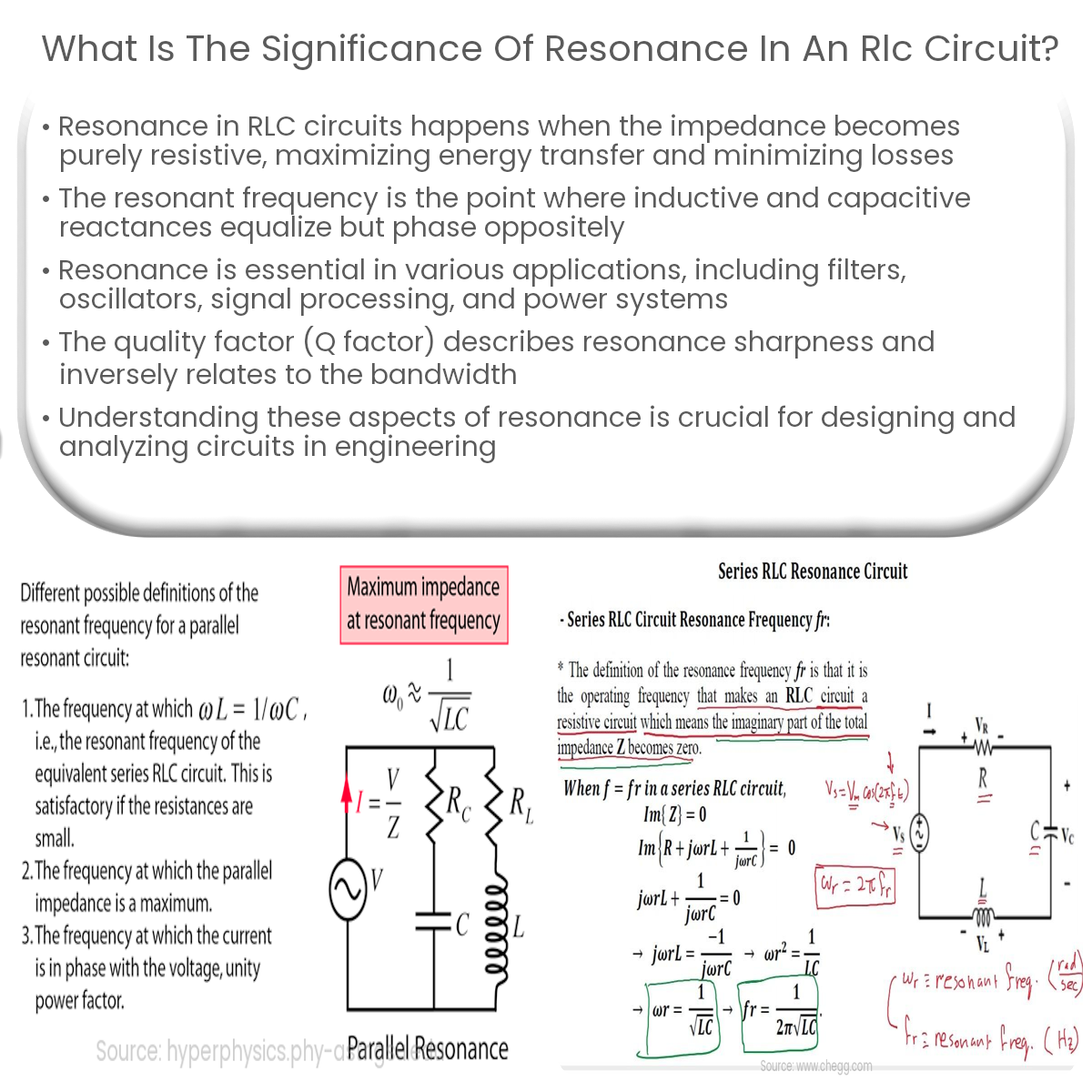
Resonance is a phenomenon that occurs in RLC circuits, where the circuit’s impedance is purely resistive and the reactive components (inductors and capacitors) cancel each other out. This leads to a maximum transfer of energy and minimal energy loss, making resonance a critical aspect of RLC circuit design and analysis.
Resonant Frequency
In an RLC circuit, the resonant frequency is the specific frequency at which the inductive and capacitive reactances are equal in magnitude but opposite in phase. At this frequency, the impedance of the inductor (jωL) is equal to the impedance of the capacitor (-j/ωC), where ω is the angular frequency, L is the inductance, and C is the capacitance.
Applications of Resonance
Resonance in RLC circuits has several practical applications:
Q Factor and Bandwidth
The quality factor, or Q factor, is a dimensionless parameter used to describe the sharpness of resonance in an RLC circuit. A higher Q factor indicates a more narrow resonant peak, which implies a lower energy loss and a more selective circuit. The bandwidth of the circuit, inversely proportional to the Q factor, is the range of frequencies over which the circuit’s response is significant. For filters and oscillators, a high Q factor is desirable for improved selectivity and stability.
Conclusion
Resonance in an RLC circuit has significant implications for the circuit’s behavior and performance. Understanding resonance and its impact on circuit design is crucial for engineers working with filters, oscillators, signal processing, and power systems. The resonant frequency, Q factor, and bandwidth are critical parameters to consider in the analysis and design of these circuits.