An ohmmeter is a type of electronic instrument used to measure the electrical resistance of a circuit element, such as a resistor or a wire. Ohmmeters work by applying a small known voltage across the element being measured and then measuring the resulting current that flows through the element. Based on Ohm’s Law, the measured current and the known voltage can be used to calculate the resistance of the element being measured.
Ohmmeters are available in different types, including analog and digital models. Analog ohmmeters use a moving needle to indicate the resistance value on a calibrated scale, while digital ohmmeters display the resistance value numerically on a digital readout. Ohmmeters may also have additional features such as the ability to measure continuity or to test diodes and other electronic components.
Ohmmeters are commonly used in electrical and electronic engineering, as well as in fields such as physics, chemistry, and materials science. They are an essential tool for troubleshooting and diagnosing problems in electronic circuits, as well as for verifying the values of resistors and other components during circuit design and assembly.
Types of Ohmmeters
There are three main types of ohmmeters: series ohmmeters, shunt ohmmeters, and digital ohmmeters.
- Series Ohmmeters: A series ohmmeter is the simplest type of ohmmeter. It consists of a current source (such as a battery), a series resistor (also called a current-limiting resistor), and a moving-coil meter. To measure the resistance of a component, the component is connected in series with the ohmmeter, and the current passing through the component is measured. The current is then displayed on the moving-coil meter, which is calibrated in ohms.
- Shunt Ohmmeters: A shunt ohmmeter is a more accurate type of ohmmeter than a series ohmmeter. It uses a shunt resistor, which is a low-value resistor that is connected in parallel with the component being measured. The voltage drop across the shunt resistor is proportional to the current passing through the component, which allows the resistance of the component to be calculated using Ohm’s Law. Shunt ohmmeters can be either analog or digital.
- Digital Ohmmeters: Digital ohmmeters use a microprocessor to measure resistance. They can be either two-wire or four-wire instruments. Two-wire ohmmeters use the same leads for both the current source and the current measurement, which can lead to errors due to contact resistance between the instrument and the component being measured. Four-wire ohmmeters use separate leads for the current source and the current measurement, which eliminates errors due to contact resistance. Digital ohmmeters can also have additional features, such as autoranging, which automatically selects the best range for the resistance being measured, and data logging, which allows the user to record resistance measurements over time.
Overall, the choice of ohmmeter depends on the accuracy and precision required for the application, as well as the budget and user experience level.
Ammeter–voltmeter method for measuring resistance
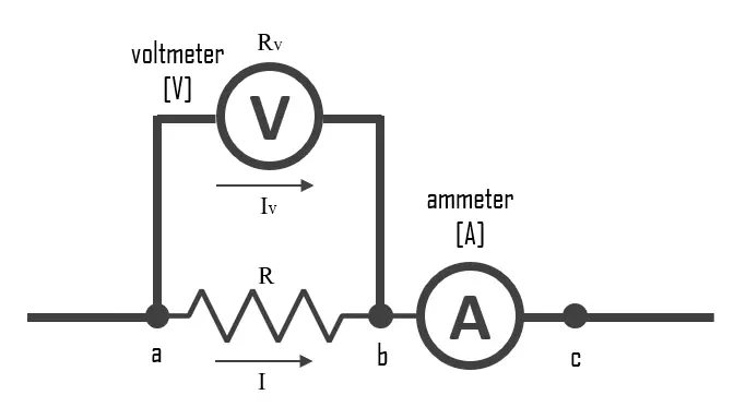
The ammeter-voltmeter method is a technique used to measure the resistance of an electrical component. It involves using an ammeter and a voltmeter in a circuit with the component whose resistance is to be measured. Here are the steps to follow:
- Disconnect the power source from the circuit.
- Connect the ammeter in series with the component whose resistance is to be measured.
- Connect the voltmeter in parallel with the component.
- Reconnect the power source to the circuit.
- Read the current on the ammeter and the voltage on the voltmeter.
- Use Ohm’s Law (R = V/I) to calculate the resistance of the component, where R is the resistance, V is the voltage across the component, and I is the current through the component.


