30-second summary
Ohmmeter
An ohmmeter is a type of electronic instrument used to measure the electrical resistance of a circuit element, such as a resistor or a wire.
In order for an ohmmeter to work properly, the circuit element being measured must be isolated from the rest of the circuit, since other components or circuits may interfere with the measurement.
There are three main types of ohmmeters: series ohmmeters, shunt ohmmeters, and digital ohmmeters.
- Series Ohmmeters
- Shunt Ohmmeters
- Digital Ohmmeters
- For example, a 60-watt bulb designed to work with a 120-volt power supply will have a resistance of approximately 240 ohms
- An electric heater typically has a resistance ranging from 10 ohms to several hundred ohms, depending on its size and power rating.
- The heating elements in an electric toaster typically have resistances ranging from 10 to 50 ohms, depending on their size and power rating.
An ohmmeter is a type of electronic instrument used to measure the electrical resistance of a circuit element, such as a resistor or a wire. Ohmmeters work by applying a small known voltage across the element being measured and then measuring the resulting current that flows through the element. Based on Ohm’s Law, the measured current and the known voltage can be used to calculate the resistance of the element being measured.
Ohmmeters are available in different types, including analog and digital models. Analog ohmmeters use a moving needle to indicate the resistance value on a calibrated scale, while digital ohmmeters display the resistance value numerically on a digital readout. Ohmmeters may also have additional features such as the ability to measure continuity or to test diodes and other electronic components.
Ohmmeters are commonly used in electrical and electronic engineering, as well as in fields such as physics, chemistry, and materials science. They are an essential tool for troubleshooting and diagnosing problems in electronic circuits, as well as for verifying the values of resistors and other components during circuit design and assembly.
How does ohmmeter work
An ohmmeter works by measuring the electrical resistance of a circuit element, such as a resistor or a wire, using a known voltage and current. Here are the basic steps involved in how an ohmmeter works:
- The ohmmeter applies a small, known voltage across the circuit element being measured. This voltage is usually generated by a battery or other power source inside the ohmmeter.
- The ohmmeter measures the current that flows through the circuit element when the voltage is applied. The current is usually measured using a current-sensing element, such as a shunt resistor or a Hall effect sensor.
- Based on Ohm’s Law, the resistance of the circuit element can be calculated using the measured voltage and current. The formula for Ohm’s Law is:R = V/IWhere: R = Resistance in ohms V = Voltage in volts I = Current in amperes
- The ohmmeter displays the calculated resistance value on a calibrated scale or digital readout.
In order for an ohmmeter to work properly, the circuit element being measured must be isolated from the rest of the circuit, since other components or circuits may interfere with the measurement. Additionally, the ohmmeter should be calibrated periodically to ensure accurate measurements. Some ohmmeters have an internal calibration feature that allows the user to adjust the calibration as needed, while others must be sent to a calibration laboratory for adjustment.
Types of Ohmmeters
There are three main types of ohmmeters: series ohmmeters, shunt ohmmeters, and digital ohmmeters.
- Series Ohmmeters: A series ohmmeter is the simplest type of ohmmeter. It consists of a current source (such as a battery), a series resistor (also called a current-limiting resistor), and a moving-coil meter. To measure the resistance of a component, the component is connected in series with the ohmmeter, and the current passing through the component is measured. The current is then displayed on the moving-coil meter, which is calibrated in ohms.
- Shunt Ohmmeters: A shunt ohmmeter is a more accurate type of ohmmeter than a series ohmmeter. It uses a shunt resistor, which is a low-value resistor that is connected in parallel with the component being measured. The voltage drop across the shunt resistor is proportional to the current passing through the component, which allows the resistance of the component to be calculated using Ohm’s Law. Shunt ohmmeters can be either analog or digital.
- Digital Ohmmeters: Digital ohmmeters use a microprocessor to measure resistance. They can be either two-wire or four-wire instruments. Two-wire ohmmeters use the same leads for both the current source and the current measurement, which can lead to errors due to contact resistance between the instrument and the component being measured. Four-wire ohmmeters use separate leads for the current source and the current measurement, which eliminates errors due to contact resistance. Digital ohmmeters can also have additional features, such as autoranging, which automatically selects the best range for the resistance being measured, and data logging, which allows the user to record resistance measurements over time.
Overall, the choice of ohmmeter depends on the accuracy and precision required for the application, as well as the budget and user experience level.
Characteristics of Ohmmeters
The characteristics of ohmmeters include:
- Accuracy: The accuracy of an ohmmeter refers to how closely it measures the true resistance value of a component. The accuracy of an ohmmeter depends on factors such as the quality of the internal components, the calibration of the instrument, and the measuring technique used.
- Precision: The precision of an ohmmeter refers to its ability to measure the same resistance value repeatedly. A precise ohmmeter will give consistent readings for the same component, while a less precise ohmmeter may give varying readings for the same component.
- Range: The range of an ohmmeter refers to the range of resistance values that it can measure. Some ohmmeters have a single range, while others have multiple ranges that can be selected depending on the resistance value of the component being measured.
- Sensitivity: The sensitivity of an ohmmeter refers to its ability to detect small changes in resistance. A more sensitive ohmmeter can detect smaller changes in resistance than a less sensitive ohmmeter.
- Speed: The speed of an ohmmeter refers to how quickly it can take a resistance measurement. Digital ohmmeters are generally faster than analog ohmmeters, since they use microprocessors to make measurements.
- Operating voltage: The operating voltage of an ohmmeter refers to the voltage required to power the instrument. Some ohmmeters run on batteries, while others require an external power source.
- User interface: The user interface of an ohmmeter refers to how easy it is to use and read the instrument. Analog ohmmeters typically have a simple, easy-to-read display, while digital ohmmeters may have additional features such as autoranging, data logging, and graphical displays.
Overall, the characteristics of an ohmmeter will depend on the specific instrument and its intended use. Different applications may require different levels of accuracy, precision, sensitivity, and speed, and users should choose an ohmmeter that meets their specific needs.
Resistance of various home devices
Here are five examples of resistance in ohms of various home devices:
- Incandescent light bulb: The resistance of an incandescent light bulb varies depending on its wattage and voltage. For example, a 60-watt bulb designed to work with a 120-volt power supply will have a resistance of approximately 240 ohms.
- Electric heater: An electric heater typically has a resistance ranging from 10 ohms to several hundred ohms, depending on its size and power rating. For example, a small 1,500-watt electric heater designed to operate on a 120-volt power supply will have a resistance of approximately 10 ohms.
- Electric stove: The heating elements in an electric stove typically have resistances ranging from 10 to 100 ohms, depending on their size and power rating. For example, a typical 8-inch burner on an electric stove may have a resistance of around 20 ohms.
- Electric iron: An electric iron typically has a resistance ranging from 10 to 30 ohms, depending on its size and power rating. For example, a typical 1,500-watt electric iron designed to operate on a 120-volt power supply will have a resistance of approximately 10 ohms.
- Electric toaster: The heating elements in an electric toaster typically have resistances ranging from 10 to 50 ohms, depending on their size and power rating. For example, a typical two-slice toaster may have heating elements with a combined resistance of around 20 ohms.
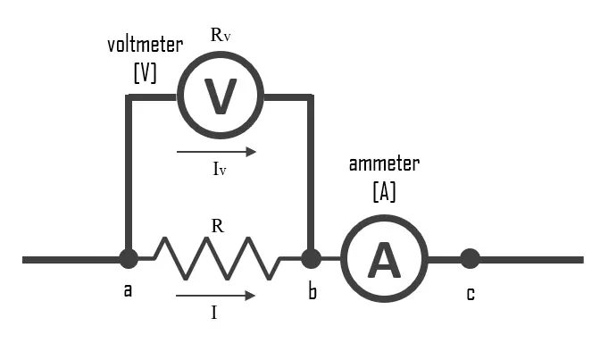
Ammeter–voltmeter method for measuring resistance
The ammeter-voltmeter method is a technique used to measure the resistance of an electrical component. It involves using an ammeter and a voltmeter in a circuit with the component whose resistance is to be measured. Here are the steps to follow:
- Disconnect the power source from the circuit.
- Connect the ammeter in series with the component whose resistance is to be measured.
- Connect the voltmeter in parallel with the component.
- Reconnect the power source to the circuit.
- Read the current on the ammeter and the voltage on the voltmeter.
- Use Ohm’s Law (R = V/I) to calculate the resistance of the component, where R is the resistance, V is the voltage across the component, and I is the current through the component.
Application of Ohmmeters
Ohmmeters are used in a variety of applications, including:
- Testing electronic components: Ohmmeters are commonly used to test the resistance of electronic components such as resistors, capacitors, and inductors. By measuring the resistance of these components, it is possible to determine if they are working properly or if they have failed.
- Troubleshooting electrical circuits: Ohmmeters can be used to troubleshoot electrical circuits by measuring the resistance of various components in the circuit. By comparing the resistance values to known values, it is possible to identify faulty components and repair the circuit.
- Testing electrical wiring: Ohmmeters can be used to test the resistance of electrical wiring, such as in buildings or vehicles. By measuring the resistance of the wiring, it is possible to determine if there are any breaks or faults in the wiring.
- Quality control in manufacturing: Ohmmeters are used in manufacturing to ensure that electronic components are within the specified resistance range. This helps to ensure that the finished products are of high quality and meet customer expectations.
- Research and development: Ohmmeters are used in research and development to test the resistance of new materials and components. This helps to determine the properties of these materials and components, and how they can be used in new products and technologies.
Overall, ohmmeters are a versatile tool that can be used in a variety of applications in electronics, electrical engineering, and manufacturing.
Ohm’s law
Ohm’s law is a fundamental principle in electrical engineering that describes the relationship between electric current, voltage, and resistance.
The law states that the current passing through a conductor between two points is directly proportional to the voltage across the two points and inversely proportional to the resistance between them. Mathematically, Ohm’s law can be expressed as:
I = V / R
where I is the current in amperes, V is the voltage in volts, and R is the resistance in ohms.
In other words, if the voltage across a conductor is increased, the current through it will also increase provided the resistance remains constant. Similarly, if the resistance is increased, the current will decrease for a given voltage. Ohm’s law is useful in designing and analyzing electrical circuits, and is one of the fundamental laws in electrical engineering.
Ohm’s law states that the R in this relation is constant and independent of the current. If the resistance is not constant, the previous equation cannot be called Ohm’s law, but it can still be used as a definition of static/DC resistance. Ohm’s law is an empirical relation that accurately describes the conductivity of the vast majority of electrically conductive materials over many orders of magnitude of the current. However, some materials do not obey Ohm’s law; these are called non-ohmic.
