Explore the RLC circuit equation, its components, significance, and an example calculation for resonant frequency, bandwidth, and quality factor.
Understanding the RLC Circuit Equation
In electrical engineering and physics, the RLC circuit equation is a fundamental equation that governs the behavior of electric circuits containing resistors (R), inductors (L), and capacitors (C). RLC circuits can be found in various applications, including signal processing, communication systems, and power distribution. In this article, we will delve into the RLC circuit equation and its significance.
Components of an RLC Circuit
- Resistor (R): A resistor is an electrical component that opposes the flow of electric current. It dissipates electrical energy in the form of heat and follows Ohm’s law, where the voltage across the resistor is directly proportional to the current flowing through it.
- Inductor (L): An inductor is a passive component that stores electrical energy in a magnetic field when electric current flows through it. It opposes any change in current and generates an electromotive force (EMF) proportional to the rate of change of current with time.
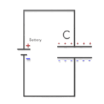
- Capacitor (C): A capacitor is a passive component that stores electrical energy in an electric field. It opposes any change in voltage across its terminals and allows alternating current (AC) to pass while blocking direct current (DC).
The RLC Circuit Equation
The RLC circuit equation is a second-order linear differential equation that describes the voltage, current, and impedance relationships in a series or parallel RLC circuit. For a series RLC circuit, the equation is derived by applying Kirchhoff’s Voltage Law (KVL), while for a parallel RLC circuit, Kirchhoff’s Current Law (KCL) is employed.
The general form of the RLC circuit equation in the time domain for a series RLC circuit is:
v(t) = R * i(t) + L * di(t)/dt + (1/C) * ∫i(t) dt
Here, v(t) represents the voltage across the circuit, i(t) is the current flowing through it, and di(t)/dt is the rate of change of current with time. In a parallel RLC circuit, the equation takes the following form:
i(t) = (1/R) * v(t) + C * dv(t)/dt + (1/L) * ∫v(t) dt
In this case, dv(t)/dt denotes the rate of change of voltage with time.
Significance of the RLC Circuit Equation
The RLC circuit equation is crucial in the analysis and design of electrical circuits, as it provides insights into the circuit’s dynamic behavior. By solving the equation, one can determine the current and voltage across various components and analyze the response of the circuit to different input signals. Furthermore, the RLC circuit equation is essential in understanding phenomena such as resonance, damping, and impedance matching, which have significant implications in circuit performance and efficiency.
Example of RLC Circuit Calculation
Let’s consider a series RLC circuit with a resistor of 200 Ω, an inductor of 0.5 H, and a capacitor of 100 μF. We will calculate the resonant frequency, bandwidth, and quality factor of the circuit.
Step 1: Calculate the Resonant Frequency
The resonant frequency (f₀) is the frequency at which the inductive reactance (XL) and capacitive reactance (XC) are equal, resulting in maximum circuit response. The formula for the resonant frequency is:
f₀ = 1 / (2π * √(LC))
Plugging in the given values, we get:
f₀ = 1 / (2π * √(0.5 * 100 * 10-6)) ≈ 318.3 Hz
Step 2: Calculate the Bandwidth
The bandwidth (BW) is the range of frequencies over which the circuit’s response is relatively constant. It can be calculated using the following formula:
BW = R / (2π * L)
Using the given values:
BW = 200 / (2π * 0.5) ≈ 63.7 Hz
Step 3: Calculate the Quality Factor
The quality factor (Q) is a dimensionless parameter that indicates the sharpness of the resonant peak and the energy loss in the circuit. A higher Q indicates a lower rate of energy loss and a more selective circuit. The formula for the quality factor is:
Q = f₀ / BW
Using the calculated values:
Q = 318.3 / 63.7 ≈ 5
In conclusion, the series RLC circuit has a resonant frequency of 318.3 Hz, a bandwidth of 63.7 Hz, and a quality factor of 5. These parameters are essential in determining the circuit’s performance and suitability for specific applications.


