30-second summary
Capacitor
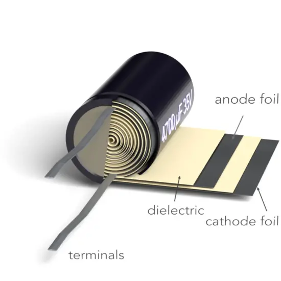
A capacitor is a device that can store electric charge and normally consists of two conducting objects (usually plates or sheets) placed near each other but not touching.
Basically, capacitors consist of two metal plates separated by an insulator. The insulator is called a dielectric. (e.g., polystyrene, oil, or air).
Capacitors are one of the most used and useful electronic components used in any modern electronic and electrical circuit and devices.
The most common kinds of capacitors are:
- Electrolytic capacitors
- Ceramic capacitors
- Paper capacitors
- Film capacitors
- Mica capacitors
- Supercapacitors
See also: Capacitance
See also: Dielectrics
Capacitor
A capacitor is a device that can store electric charge and normally consists of two conducting objects (usually plates or sheets) placed near each other but not touching. Basically, capacitors consist of two metal plates separated by an insulator. The insulator is called a dielectric. (e.g., polystyrene, oil, or air). Capacitors are one of the most used and useful electronic components used in any modern electronic and electrical circuit and devices.
Their capacitance depends only on the size, shape, and relative position of the two conductors, and also on the material that separates them.
A simple capacitor consists of a pair of parallel plates of area A separated by a small distance d. Often the two plates are rolled into the form of a cylinder with plastic, paper, or other insulator separating the plates.
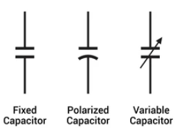
In circuit diagrams, a capacitor is represented by either of these symbols:
Types of Capacitors
Capacitors are divided into three basic groups:
- Fixed capacitors. The capacitors whose value is fixed during the manufacturing process and cannot be latter altered are called fixed capacitors. Fixed capacitors are also further classified into two kinds, electrolytic and non-electrolytic capacitors.
- Polarized capacitors. Polarized Capacitors are the ones that have specific positive and negative polarities. While using these capacitors in circuits, it should always be taken care that they are connected in perfect polarities.
- Variable capacitors with a variable capacitance. They are made as trimmers that are typically adjusted only during circuit calibration, and as a device tunable during the operation of the electronic instrument.
The most common group is fixed capacitors. Many are named based on the type of dielectric. For a systematic classification, these characteristics cannot be used because one of the oldest, the electrolytic capacitor, is named instead by its cathode construction.
The most common kinds of capacitors are:
- Electrolytic capacitors
- Ceramic capacitors
- Paper capacitors
- Film capacitors
- Mica capacitors
- Supercapacitors
- ….
Typical Values
One farad of capacitance is a relatively large unit of capacitance, and it is not commonly found in most electronic circuits. A capacitor with a capacitance of one farad can store one coulomb (C) of charge per volt of potential difference between its plates. Submultiples of the farad, such as the microfarad and the picofarad, are more convenient units in practice.
To give you an idea of how large one farad is, consider the following examples:
- A typical small ceramic capacitor used in electronics might have a capacitance of around 0.1 microfarads (µF), which is one ten-millionth of a farad.
- A typical electrolytic capacitor used in power supply circuits might have a capacitance of a few hundred or thousand microfarads (µF), which is still many orders of magnitude smaller than one farad.
- A supercapacitor or ultracapacitor, which is a type of high-capacity capacitor used in some energy storage applications, might have a capacitance of several farads or even tens of farads.
In summary, one farad of capacitance is a relatively large unit of capacitance, and capacitors with capacitances in the farad range are typically only used in specialized applications. Most electronic circuits use capacitors with capacitances in the microfarad or picofarad range.
Application of Capacitors
Capacitors are used in a wide range of electronic and electrical applications due to their ability to store and release electrical energy. Some of the most common applications of capacitors include:
- Energy storage: Capacitors are used to store electrical energy in electronic circuits. They can be used to smooth out voltage fluctuations in power supply circuits, and in combination with other components, can be used to filter unwanted noise or interference from a signal.
- Timing: Capacitors are commonly used in timing circuits, such as oscillators, to control the frequency and duration of electrical signals.
- Power factor correction: Capacitors can be used in power factor correction circuits to improve the efficiency of electrical systems by reducing the amount of reactive power drawn from the grid.
- Motor starting and power conditioning: Capacitors can be used in electric motors to provide starting torque and improve the power factor of the motor.
- Audio and signal processing: Capacitors are used in audio and signal processing circuits to filter and tune signals, and to couple signals between different stages of a circuit.
- Radio frequency (RF) circuits: Capacitors are used in RF circuits to block DC signals while allowing AC signals to pass through, and to tune resonant circuits.
- Sensors: Capacitive sensors use changes in capacitance to detect changes in position, pressure, humidity, and other environmental factors.
These are just a few examples of the many applications of capacitors. Capacitors are versatile components that are widely used in electronics and electrical systems, and new applications for capacitors are constantly being developed.
Calculation of Capacitors
For example, the capacitance of flat, parallel metallic plates of area A and separation d is given by the expression below:
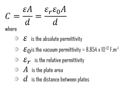
As can be seen, the permittivity is often represented by the relative permittivity εr or κ which is the ratio of the absolute permittivity ε and the vacuum permittivity ε0.
εr = κ = ε/ε0
Example:
The parallel plates of a ?1F capacitor are 1.0 mm apart in a vacuum. What is their area?
This problem uses the relationship among the capacitance C, plate separation d, and plate area A for a parallel-plate capacitor. We solve the equation for parallel-plate capacitor.
A = C.d/ε0 = 1.1 x 10² m2
That’s quite a large area. In reality, the capacitor can be much smaller. The trick is to have an appropriate substance between the plates rather than a vacuum, so that the plate separation d can greatly reduced.
Capacitors in series and parallel
Capacitors may be combined in series or parallel. The following figure shows three capacitors connected in series and connected to an electric source. Theoretically, the equivalent capacitance for the series connection is given by:
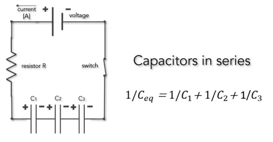
In the case of series connection of capacitors, the reciprocal of the equivalent capacitance is equal to the sum of the reciprocals of the capacitances of the capacitors.
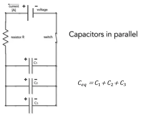
In the case of parallel connection of capacitors, the equivalent capacity is equal to the sum of the capacities of the capacitors.
Charging a Capacitor
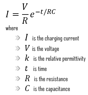
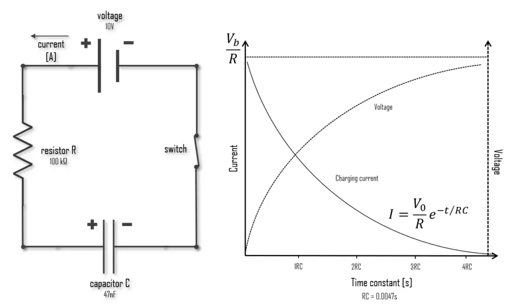
In most practical applications, each conductor of a capacitor initially has zero net charge. If we connect a capacitor, a resistor, and a voltage source in series, the capacitor will be charged up until its voltage value is equal to the voltage source. A capacitor can store energy, and a resistor placed in series with it will control the rate at which it charges or discharges. This produces a characteristic time dependence and a crucial parameter that describes a capacitor’s rate of charge and discharge:
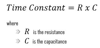
The time constant, or circuit time delay, represents the time response of the circuit when an input step voltage or signal is applied.
The charging current asymptotically approaches zero as the capacitor becomes charged up to the battery voltage. The time required for the capacitor to be fully charged is equivalent to about 5 time constants or 5T. Thus, the transient response or a series RC circuit is equivalent to 5 time constants.
Capacitors together with resistors, form so-called RC circuits, and they are a common element in electronic devices and play an important role in the transmission of electrical signals. They are used to control the speed of a car’s windshield wipers and the timing of traffic lights; they are used in camera flashes and in many other electronic devices, such as audio filters and oscillators.
Discharging a Capacitor
Discharging a capacitor means releasing the charge stored within the capacitor. RC discharging circuits use the inherent RC time constant of the resistor-capacitor combination to discharge a capacitor at an exponential rate of decay.
Energy stored in Capacitor
Capacitors can be used to store electrical energy. Many of the most important applications of capacitors depend on their ability to store energy. The electric potential energy stored in a charged capacitor is just equal to the amount of work required to charge it—that is, to separate opposite charges and place them on different conductors. When the capacitor is discharged, this stored energy is recovered as work done by electrical forces.
It can be derived that if, at the end of the charging process, the charge on the top plate is +Q, then the total amount of work done in this process is:
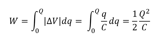
This is also equal to the total work done by the electric field on the charge when the capacitor discharges.
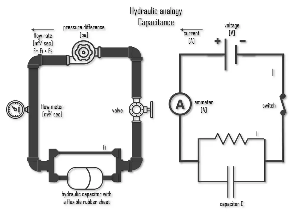
Capacitors in Hydraulic Analogy
In a hydraulic analogy, capacitors are equivalent to a tank with one connection at each end and a membrane dividing the tank in two lengthwise (a hydraulic accumulator). As the pump in the system begins pushing water, the membrane will stretch in response to the pressure from said water. The significance of the stretching is comparable to the amount of charge deposited on a capacitor. It should be fairly easy to see from this description that this membrane’s stretching represents the voltage drop in an electrical circuit, and the discharge of a capacitor is likewise comparable to the membrane returning to its original extent.
Capacitor with a Dielectric
Dielectrics have many applications, but the most significant use is in capacitors. In many capacitors, there is an insulating material such as paper or plastic between the plates. Such a material, called a dielectric, can be used to maintain a physical separation of the plates.
Placing a solid dielectric between the plates of a capacitor serves three functions.
- Mechanical separation
- Electrical isolation – higher voltage possible
- Electric field reduction – higher capacitance
First, it solves the mechanical problem of maintaining two large metal sheets at a very small separation without actual contact.
Second, using a dielectric increases the maximum possible potential difference between the capacitor plates. Any insulating material, when subjected to a sufficiently large electric field, experiences a partial ionization that permits conduction through it. This is called dielectric breakdown. Note that, the dielectric strength of air is approximately 3 kV/mm. Many dielectric materials can tolerate stronger electric fields without breakdown than can air. Thus using a dielectric allows a capacitor to sustain a higher potential difference and so store greater amounts of charge and energy.
Third, experimentally it was found that capacitance C increases when the space between the conductors is filled with dielectrics. The polarisation of the dielectric by the applied electric field increases the capacitor’s surface charge for the given electric field strength. Application of an electric field between the two plates induces some opposite charge on the dielectric, which opposes the applied electric field. The net result is that the electric field inside the dielectric (which fills the area between the plates) is reduced, allowing the capacitor to store more charge.
To see how this happens, suppose a capacitor has a capacitance when there is no material between the plates. When a dielectric material is inserted to completely fill the space between the plates, the capacitance increases to:
C = κeC0
where κe is called the dielectric constant.
As can be seen, there are two cases. If the potential difference between the plates of a capacitor is maintained, as by battery B, the effect of a dielectric is to increase the charge on the plates. (b) If the charge on the capacitor plates is maintained, as in this case, the effect of a dielectric is to reduce the potential difference between the plates.

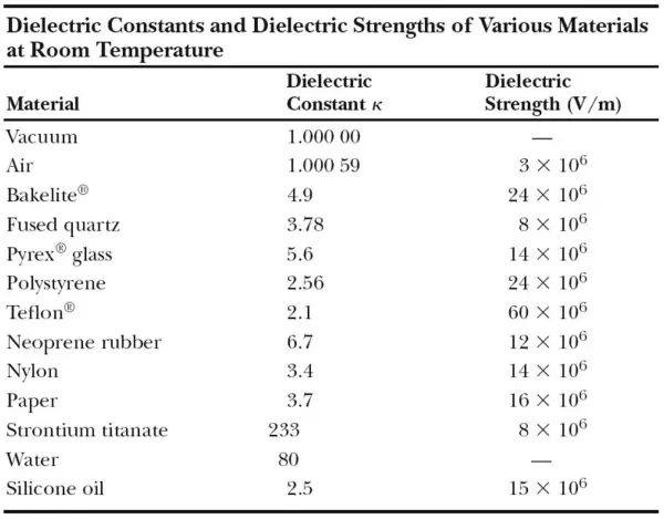
In the table below, we show some dielectric materials with their dielectric constant. Experiments indicate that all dielectric materials have κe > 1. Note that every dielectric material has a characteristic dielectric strength which is the maximum value of the electric field before breakdown occurs and charges begin to flow.