Explore the principles, applications, and pros & cons of JK Flip-Flops, fundamental devices in digital circuits and memory systems.
Introduction to JK Flip-Flops
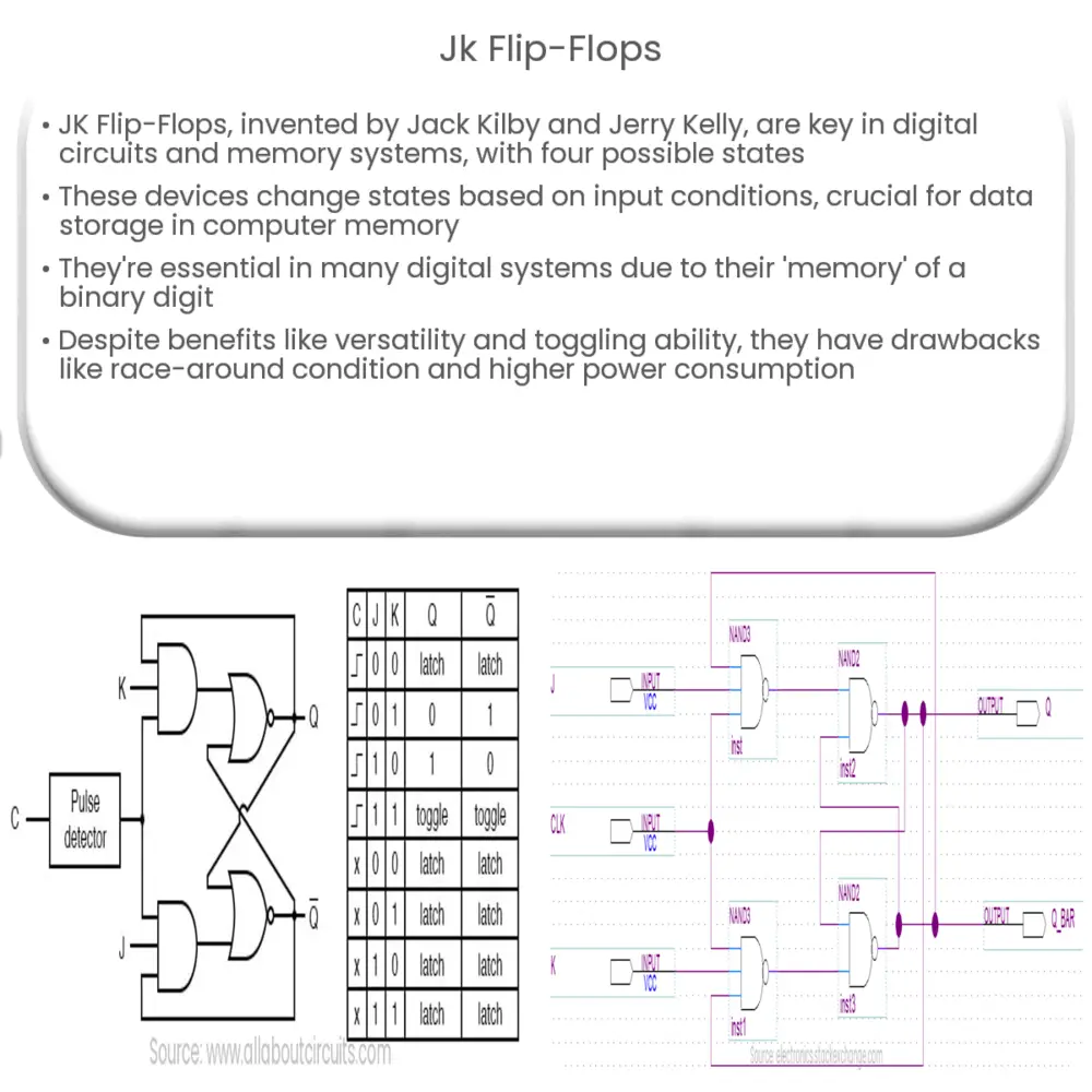
The JK Flip-Flop, named after its inventors Jack Kilby and Jerry Kelly, is a fundamental component in digital circuits and computer memory systems. The flip-flop is a type of bi-stable multivibrator, meaning it has two stable states which it can flip (or toggle) between under the right conditions.
A JK Flip-Flop can exist in one of four states: no change (when J=0, K=0), reset (when J=0, K=1), set (when J=1, K=0), and toggle (when J=1, K=1). Here, J and K are the input conditions and stand for Jack and Kilby, respectively.
Working Principle of JK Flip-Flops
The JK Flip-Flop consists of a basic latch (comprising two cross-coupled NOR gates or NAND gates) supplemented with additional gates to control the latch operation. The J (Set) and K (Reset) inputs are responsible for altering the states of the flip-flop.
- State 1: No change (J=0, K=0) – The outputs remain the same irrespective of the previous state.
- State 2: Set (J=1, K=0) – The flip-flop is set, and the output Q is driven high (Q=1).
- State 3: Reset (J=0, K=1) – The flip-flop is reset, and the output Q is driven low (Q=0).
- State 4: Toggle (J=1, K=1) – The outputs toggle (i.e., they switch states).
Timing Diagram of JK Flip-Flop
The timing diagram of a JK Flip-Flop illustrates the sequence of inputs J, K, and the clock pulse (CLK), along with the outputs Q and Q’. The timing diagram is essential in understanding the behavior of the JK Flip-Flop with different input signals over time.
- CLK: The Clock pulse which synchronizes the operation of the flip flop.
- J and K: The input signals.
- Q and Q’: The flip-flop outputs. Q’ is the inverse of Q, also called NOT Q.
Every time the clock changes state, the flip-flop checks the J and K inputs. Depending on their values, the flip-flop will either change its state or maintain the current state. This mechanism forms the basis for how computer memory stores data.
Applications of JK Flip-Flops
The versatility and functionality of JK Flip-Flops make them an essential part of various digital systems. They have widespread applications due to their capability to ‘remember’ a binary digit or bit.
- Memory Devices: One of the most important uses of JK Flip-Flops is in Random Access Memory (RAM) of computers, where they serve as memory units to store data.
- Counters: Flip-flops, particularly JK Flip-Flops, are used to build binary counters and frequency dividers due to their toggle feature.
- Shift Registers: JK Flip-Flops can be used to make shift registers, which are essential for data storage and transfer in digital systems.
- Control Systems: They are used in control systems for controlling the sequence of operation.
Advantages and Disadvantages of JK Flip-Flops
While JK Flip-Flops offer numerous advantages, they are not without their downsides.
- Advantages:
- Due to their toggling feature, JK Flip-Flops can change states without requiring any specific change in the input signals.
- They are versatile and can perform all the operations of SR and D Flip-Flops.
- Disadvantages:
- The main drawback of JK Flip-Flops is the occurrence of the race around condition, which happens when the output repeatedly toggles between states within one clock cycle.
- They are more complex and have a higher gate count than other types of flip-flops, leading to increased power consumption.
Conclusion
In the world of digital electronics, JK Flip-Flops play an indispensable role. With their ability to remember states and toggle between them, these devices form the core of digital memory systems. While they possess certain disadvantages like the race around condition and increased complexity, their benefits often outweigh these shortcomings, making them integral to modern digital systems. From computer memory to control systems, JK Flip-Flops continue to be the fundamental building blocks of numerous digital devices and circuits.
