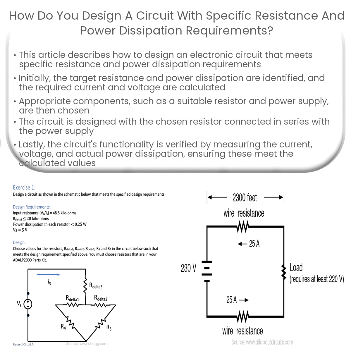
To design a circuit with specific resistance and power dissipation, choose appropriate components, create a series connection, and verify the circuit.
Designing a Circuit with Specific Resistance and Power Dissipation Requirements
When designing an electronic circuit, it is often necessary to meet specific resistance and power dissipation requirements. This article will outline the steps to take in order to achieve these goals.
Step 1: Determine the Resistance and Power Dissipation Requirements
- Identify the target resistance (Rtarget) and power dissipation (Pdissipation) for the circuit.
- Calculate the required current (I) and voltage (V) across the resistor using Ohm’s Law (V = IR) and the power dissipation formula (P = IV).
Step 2: Choose Appropriate Components
- Resistor: Select a resistor with the desired resistance value (Rtarget) and a power rating higher than the calculated power dissipation (Pdissipation). This ensures the resistor can handle the required current and voltage without overheating.
- Power supply: Choose a power supply capable of providing the necessary voltage and current for the circuit.
Step 3: Design the Circuit
Design the circuit so that the chosen resistor is connected in series with the power supply, ensuring the voltage across the resistor (VR) is equal to the desired voltage (V). This can be achieved by following these steps:
- Connect the positive terminal of the power supply to one end of the resistor.
- Connect the other end of the resistor to the negative terminal of the power supply.
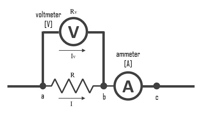
- Use a multimeter to measure the voltage across the resistor (VR) and ensure it is equal to the desired voltage (V).
Step 4: Verify the Circuit
After assembling the circuit, verify its functionality by following these steps:
- Measure the current (I) flowing through the circuit with an ammeter.
- Verify that the measured current (I) is equal to the calculated current from Step 1.
- Measure the voltage across the resistor (VR) and ensure it is equal to the desired voltage (V).
- Calculate the power dissipation (Pactual) using the measured current (I) and voltage (VR).
- Confirm that the actual power dissipation (Pactual) is equal to or less than the desired power dissipation (Pdissipation).
By following these steps, you can design a circuit that meets specific resistance and power dissipation requirements, ensuring the proper functionality and reliability of your electronic devices.


