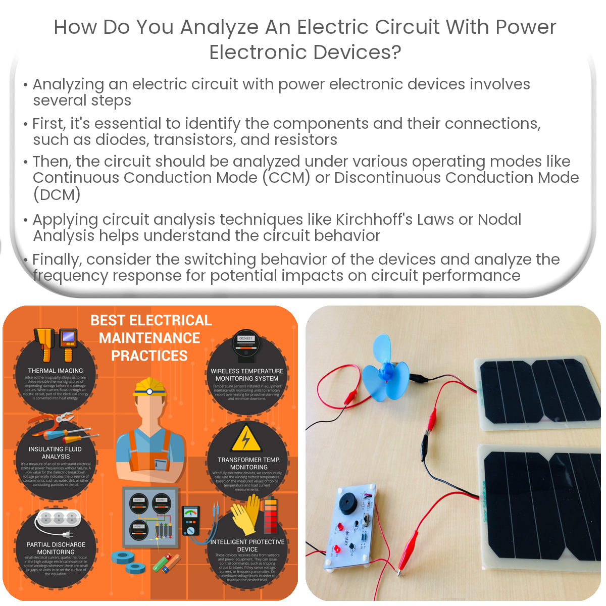
To analyze an electric circuit with power electronic devices, identify components, determine operating modes, apply circuit analysis techniques, consider switching behavior, and analyze frequency response.
How to Analyze an Electric Circuit with Power Electronic Devices
Power electronic devices play a crucial role in modern electric circuits, enabling efficient control and conversion of electrical energy. When analyzing an electric circuit with power electronic devices, it is essential to understand the basic principles and techniques. In this article, we will explore the key steps to effectively analyze such a circuit.
1. Identify the Components and Their Connections
- Recognize the power electronic devices used in the circuit, such as diodes, transistors, thyristors, or MOSFETs.
- Examine the passive components, including resistors, capacitors, and inductors.
- Study the interconnections between the components and establish the overall circuit topology.
2. Analyze the Circuit in Different Modes
Power electronic circuits typically operate in different modes, depending on the input voltage and current conditions. These modes may include:
- Continuous conduction mode (CCM)
- Discontinuous conduction mode (DCM)
- Boundary conduction mode (BCM)
Determine the appropriate mode for your analysis based on the operating conditions of the circuit.
3. Apply Circuit Analysis Techniques
Employ various circuit analysis techniques, such as:
- Kirchhoff’s Laws: Apply Kirchhoff’s Current Law (KCL) and Kirchhoff’s Voltage Law (KVL) to analyze the circuit behavior in terms of currents and voltages.
- Nodal Analysis: Use nodal analysis to determine the voltage at each node in the circuit.
- Mesh Analysis: Utilize mesh analysis to calculate the current flowing through each loop in the circuit.
- Thevenin’s Theorem: Apply Thevenin’s theorem to simplify complex circuits and determine the equivalent voltage and resistance.
4. Consider Switching Behavior
Power electronic devices often exhibit switching behavior, which can lead to non-linear circuit responses. To account for this:
- Study the switching characteristics of the devices, such as turn-on and turn-off times, and voltage and current ratings.
- Understand the impact of switching losses and conduction losses on the overall circuit efficiency.
5. Analyze the Frequency Response
Power electronic circuits often involve AC-DC or DC-AC conversion, making it important to analyze the frequency response. To do so:
- Identify the harmonics generated by the power electronic devices.
- Examine the impact of these harmonics on the overall circuit performance, including power quality and electromagnetic compatibility (EMC).
In conclusion, analyzing an electric circuit with power electronic devices involves identifying the components and their connections, determining the appropriate mode of operation, applying various circuit analysis techniques, accounting for switching behavior, and analyzing the frequency response. By following these steps, engineers can effectively design and optimize power electronic circuits for various applications.