Explore the basics of half-wave rectifiers, their functioning, applications, limitations, and how they fit into the broader electronics landscape.

Understanding Half-Wave Rectifiers
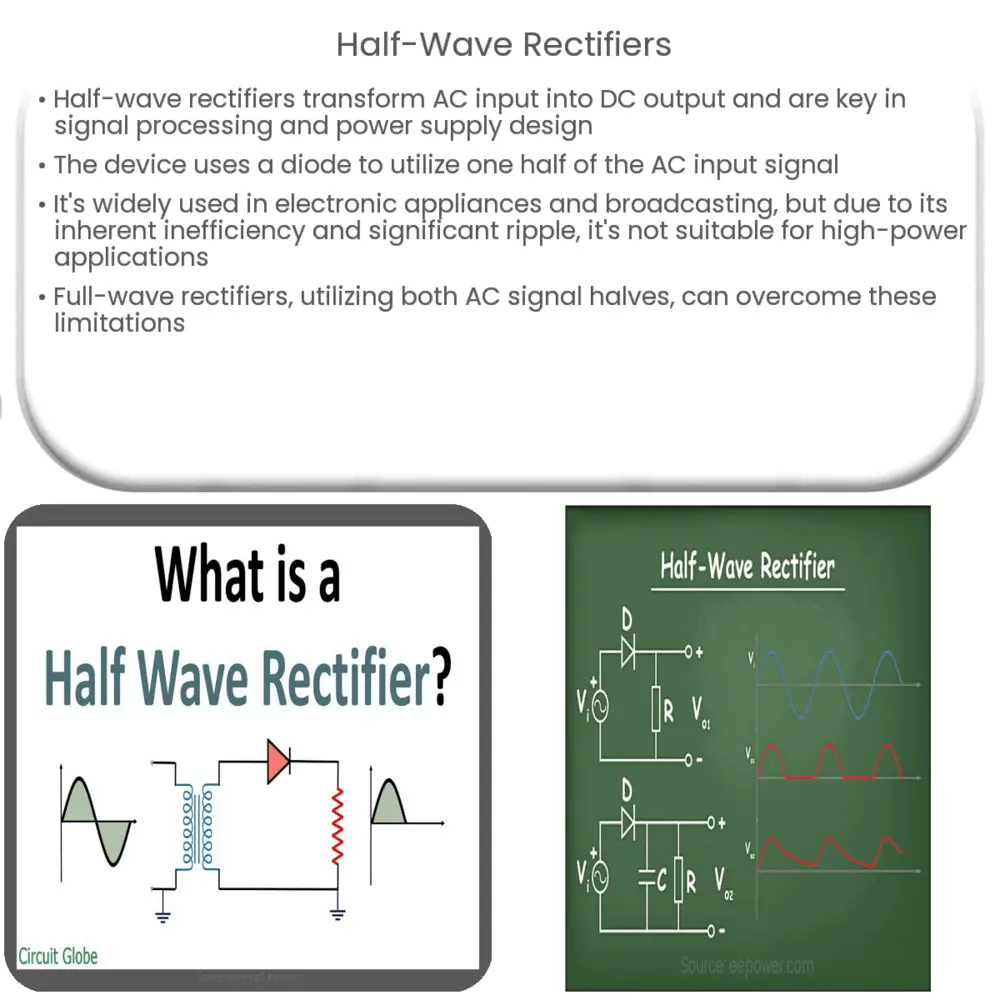
A half-wave rectifier is an electronic device used extensively in signal processing and power supply design. This fundamental concept in electronics transforms an alternating current (AC) input into a direct current (DC) output. While the transformation is not perfect—often containing ripples—the device provides a substantial step towards achieving a constant DC signal.
Basic Functioning of a Half-Wave Rectifier
The half-wave rectifier gets its name from its operation. Out of the full cycle of the AC input signal, it utilizes only one half—either positive or negative. The primary component in a simple half-wave rectifier is a diode, which is a semiconductor device that allows current flow in one direction only. Hence, the diode becomes forward-biased (conducts) during one half of the AC cycle and reverse-biased (does not conduct) during the other half.
- Positive Half Cycle: In this cycle, the diode is forward-biased, and current is allowed to pass, which is then represented in the output.
- Negative Half Cycle: In this cycle, the diode is reverse-biased, preventing current flow. This half cycle gets ‘clipped’ off and does not appear in the output.
Circuit Design and Operation
Creating a simple half-wave rectifier involves connecting an AC signal input, a diode, and a resistor for load. During the positive half cycle of AC signal, the diode becomes forward-biased, allowing current to flow from the diode to the resistor. Conversely, during the negative half cycle, the diode becomes reverse-biased, blocking the current flow.
Consequently, only half of the waveform, the positive or negative half depending on the orientation of the diode, appears across the load. The other half of the AC signal is effectively removed. Therefore, the output signal is a DC signal with a frequency identical to the input signal, but only half the amplitude.
Applications of Half-Wave Rectifiers
Half-wave rectifiers find extensive application in several electronic devices. They serve as the primary component in power supplies for electronic appliances, providing the necessary DC output. Additionally, they’re used in signal detection and signal modulation processes, which form the basis of radio and television broadcasting.
Limitations of Half-Wave Rectifiers
Despite their widespread use, half-wave rectifiers have some notable limitations. First and foremost, they only use one half of the AC signal, making them inherently inefficient. The missing half of the AC waveform results in a significant ripple in the DC output, which often requires additional filtering to achieve a smooth DC signal.
Moreover, half-wave rectifiers may not be suitable for high-power applications due to the strain on the diode. During the blocked half cycle, all the voltage appears across the diode, increasing the peak inverse voltage (PIV) requirements of the diode.
Overcoming the Limitations
To overcome these limitations, full-wave rectifiers are often used. A full-wave rectifier utilizes both the positive and negative half cycles of the AC signal, increasing the efficiency and reducing the ripple in the output signal. While the circuit design is slightly more complex, the improved performance often justifies the additional complexity.
Conclusion
In conclusion, half-wave rectifiers are a fundamental component in electronics, offering an efficient means to convert an AC signal into a DC signal. Despite their limitations, such as significant ripple and inefficiency due to using only half the AC waveform, they are extensively used in various applications, including power supply units and signal detection systems. However, in high-power applications or where smooth DC output is required, full-wave rectifiers are often the preferred choice. Understanding half-wave rectifiers and their role provides a strong foundation for grasping more complex electronics concepts.


