
Explore the intricacies of Capacitive Sample-and-Hold Circuits, their key components, functioning, and significant applications in digital systems.
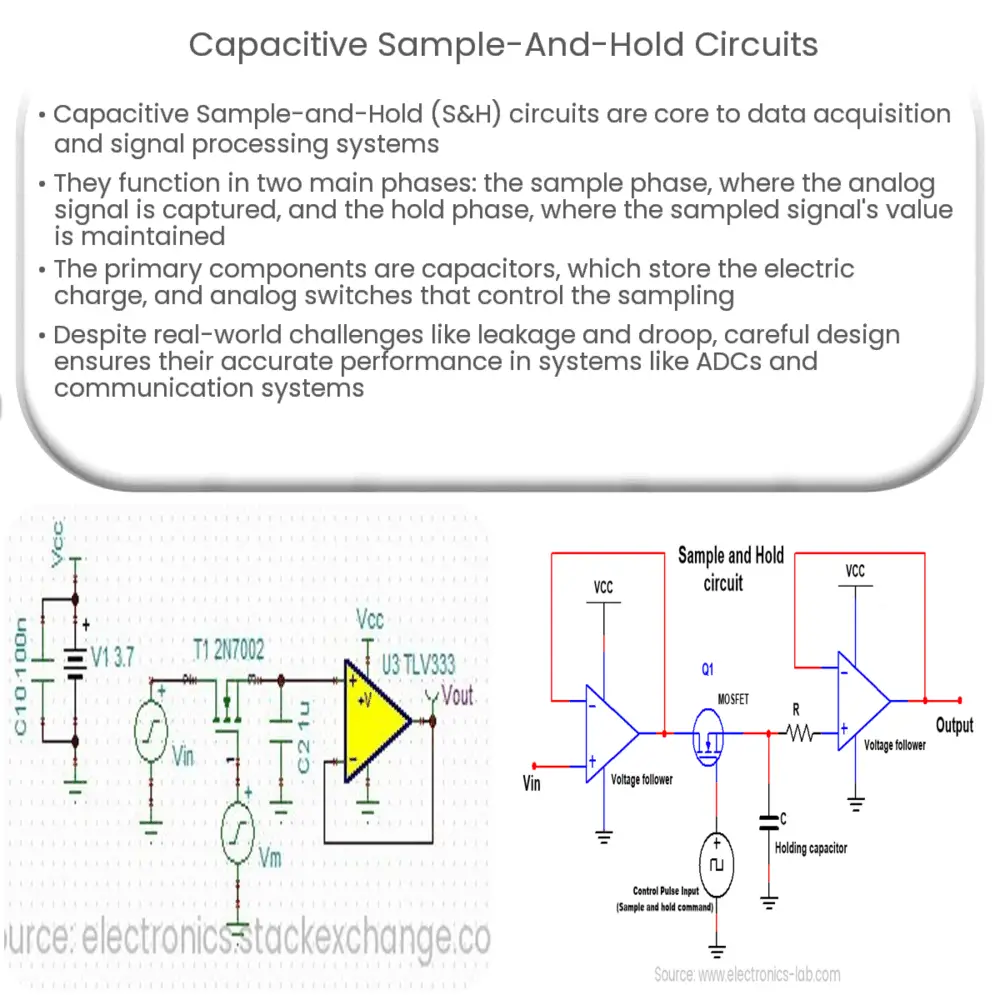
Understanding Capacitive Sample-and-Hold Circuits
The heart of data acquisition and signal processing systems is the Capacitive Sample-and-Hold Circuit. This vital component, often abbreviated as S/H or S&H, is designed to sample an analog signal and hold onto its value for a certain period of time, enabling subsequent stages of the system to process the sampled signal appropriately.
Principle of Operation
A typical sample-and-hold circuit comprises of an analog switch and a capacitor. The analog switch is responsible for sampling the input signal, while the capacitor holds the sampled signal for a given duration. The operation of the S&H circuit is largely categorized into two phases, as explained below:
- Sample Phase: During this phase, the analog switch is closed, which allows the circuit to sample the input signal. The voltage across the capacitor equates to the instantaneous value of the input signal at the moment the sampling begins.
- Hold Phase: In the hold phase, the analog switch is opened, and the capacitor starts to maintain or hold the last sampled voltage. The output during this phase represents the sampled input signal.
Capacitive Sample-and-Hold Circuits
The primary factor that sets capacitive sample-and-hold circuits apart is the utilization of capacitors. Capacitors are fundamental in these circuits because they can store electric charge, which translates into the ability to maintain voltage levels. This feature makes them excellent elements for ‘holding’ the sampled signal value.
In capacitive S&H circuits, the capacitor’s value is a significant parameter. Ideally, it should be large enough to ensure that the voltage doesn’t drop significantly during the hold phase. However, a larger capacitor might lead to longer charging and discharging times, which can pose problems at high-frequency operations.
It’s also crucial to note that in real-world applications, the capacitor cannot hold the charge indefinitely due to leakage currents and finite input impedance of the following stages. These factors introduce errors known as droop or leakage errors, which must be carefully managed to ensure accurate data acquisition and signal processing.
Key Components of Capacitive Sample-and-Hold Circuits
The key components that make up a capacitive sample-and-hold circuit are:
- Capacitor: As explained earlier, this component is used to hold the voltage of the sampled signal.
- Analog Switch: This is used to sample the signal when closed and isolate the capacitor during the hold phase when opened.
The Functioning of Key Components
The operation of these key components can be further elaborated as follows:
- Capacitor: The capacitor charges or discharges until it reaches the input voltage level during the sampling phase. Once the switch opens, the capacitor retains its voltage, essentially ‘holding’ the sampled value. However, the capacitor slowly loses its charge over time due to the natural phenomenon of leakage, causing a slight decline in voltage known as the droop.
- Analog Switch: The analog switch is essentially a high-speed transistor operating as a switch. During the sample phase, the switch is ‘closed’ (conducting), allowing the capacitor to charge to the input signal level. When the circuit enters the hold phase, the switch ‘opens’ (non-conducting), isolating the capacitor and enabling it to hold the sampled value.
Applications of Capacitive Sample-and-Hold Circuits
Capacitive sample-and-hold circuits find wide-ranging applications in digital systems that interface with the analog world. These include:
- Analog-to-Digital Converters (ADCs): Capacitive S&H circuits are used extensively in ADCs to sample the analog input before it’s converted to a digital representation.
- Communication Systems: S&H circuits are employed in communication systems, where they aid in the demodulation of pulse-amplitude modulated (PAM) signals.
Conclusion
In conclusion, capacitive sample-and-hold circuits are integral components of many digital systems that interact with analog signals. The two primary components of these circuits, the capacitor and the analog switch, work in unison to sample and hold an input signal for a specified duration, thus making it possible for the subsequent stages of the system to process this sampled signal at their own pace.
Despite the challenges posed by real-world factors such as leakage and droop, careful design and selection of components can ensure these circuits deliver accurate and reliable performance. With their significant role in ADCs and communication systems, capacitive S&H circuits continue to remain a vital technology in our increasingly digital world.