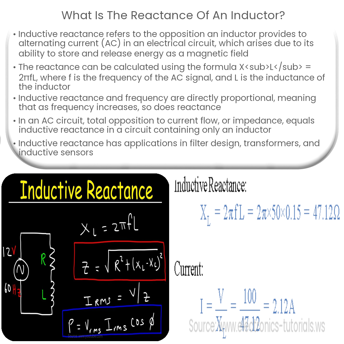
Inductive reactance is the opposition an inductor provides to AC current flow. Calculate it using the formula: Xₗ = 2πfL, where f is frequency, L is inductance.
Understanding Inductive Reactance
Inductive reactance is a measure of the opposition an inductor provides to the flow of alternating current (AC) in an electrical circuit. Inductors, which consist of a coil of wire wound around a core, exhibit this property due to their inherent ability to store and release energy in the form of a magnetic field. When an AC voltage is applied across an inductor, the resulting current flowing through it creates a time-varying magnetic field that opposes any change in the current. This opposition is known as inductive reactance.
Calculating Inductive Reactance
To calculate the inductive reactance (XL) of an inductor, the following formula is used:
XL = 2πfL
In this equation, f represents the frequency of the AC signal in hertz (Hz), and L is the inductance of the inductor in henrys (H). The product of 2π and the frequency is also known as the angular frequency (ω).
Inductive Reactance and Frequency
The relationship between inductive reactance and frequency is directly proportional, meaning that as the frequency of the AC signal increases, the inductive reactance also increases. Conversely, when the frequency decreases, so does the inductive reactance. At very low frequencies or in DC circuits, the inductive reactance is negligible, and the inductor behaves like a short circuit.
Impedance and Inductive Reactance
In an AC circuit, impedance (Z) represents the total opposition to the flow of current, taking into account both resistance (R) and reactance (X). For a circuit containing only an inductor, the impedance is equal to the inductive reactance:
Z = XL
However, in circuits containing resistors, capacitors, and inductors, the impedance must be calculated using the following formula:
Z = √(R² + (XL – XC)²)
Where XC represents the capacitive reactance.
Applications of Inductive Reactance
- Filters: Inductive reactance is used in designing various filter circuits, such as low-pass, high-pass, band-pass, and band-stop filters.
- Transformers: Transformers rely on the concept of inductive reactance to transfer electrical energy between circuits via magnetic coupling.
- Inductive sensors: The change in inductive reactance with varying physical parameters, such as position or proximity, enables the development of inductive sensors for various applications.