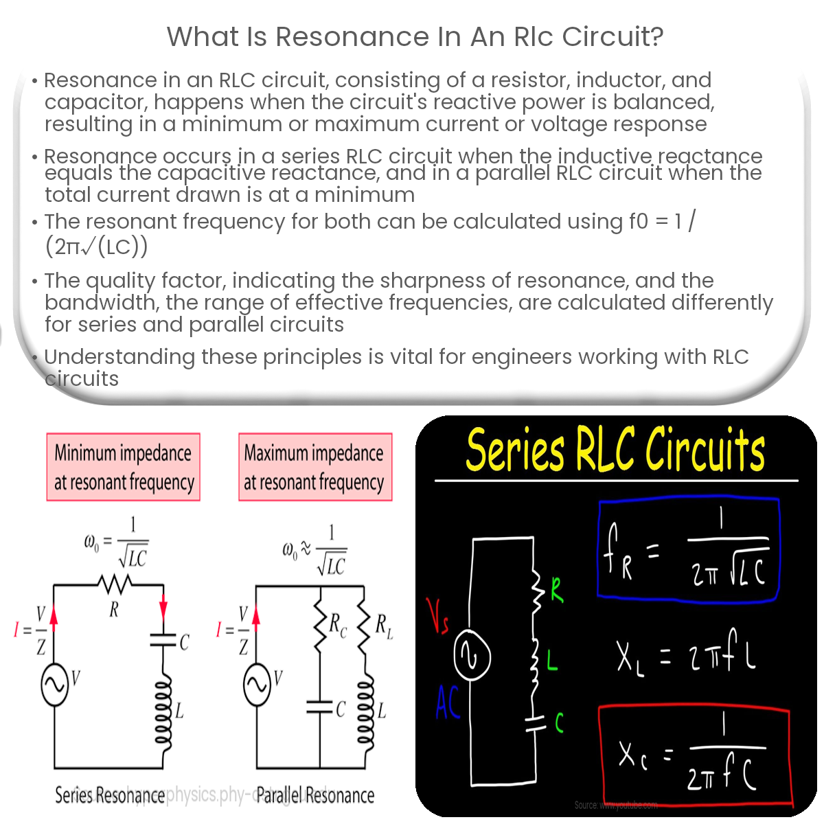
Resonance in an RLC circuit occurs when the reactive power from the inductor and capacitor cancel each other, resulting in minimum or maximum response.
Resonance in an RLC Circuit
Resonance is a fundamental concept in electrical engineering, particularly in the context of RLC circuits. An RLC circuit consists of a resistor (R), an inductor (L), and a capacitor (C) connected in series or parallel. Resonance occurs when the circuit’s reactive power, contributed by the inductor and capacitor, is equal and opposite, resulting in a minimum or maximum current or voltage response.
Series Resonance
In a series RLC circuit, resonance occurs when the inductive reactance (XL) is equal to the capacitive reactance (XC). At this point, the circuit’s impedance is purely resistive, and the current passing through the circuit is at its maximum. This is known as the resonant frequency (f0), which can be calculated using the following formula:
f0 = 1 / (2π√(LC))
Series resonance has numerous applications, including tuning circuits, filters, and impedance matching.
Parallel Resonance
Parallel resonance occurs in a parallel RLC circuit when the total current drawn from the source is at a minimum. This happens when the inductive and capacitive currents are equal and opposite, effectively canceling each other out. The resonant frequency for a parallel RLC circuit can also be calculated using the same formula as for series resonance:
f0 = 1 / (2π√(LC))
Parallel resonance has applications in band-stop filters, impedance matching, and noise suppression.
Quality Factor and Bandwidth
The quality factor (Q) of an RLC circuit is a dimensionless parameter that indicates the sharpness of the resonance. A higher Q value signifies a more selective circuit, with a narrow bandwidth and a sharp resonant peak. The quality factor for a series RLC circuit can be calculated using:
Q = (1 / R) √(L / C)
For a parallel RLC circuit, the formula is:
Q = R √(C / L)
The bandwidth of the circuit is the range of frequencies over which the circuit operates effectively. The relationship between the quality factor and the bandwidth is given by:
Bandwidth = f0 / Q
In summary, resonance in an RLC circuit is a crucial phenomenon with significant implications in various applications, including filtering, impedance matching, and tuning. Understanding the concepts of series and parallel resonance, resonant frequency, quality factor, and bandwidth is essential for engineers working with RLC circuits.