An RLC circuit is an electrical circuit consisting of resistors, inductors, and capacitors, used in applications like filtering, oscillators, and impedance matching.
Introduction to RLC Circuits
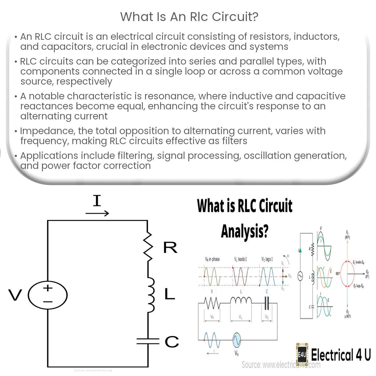
An RLC circuit is an electrical circuit that consists of resistors (R), inductors (L), and capacitors (C). These three components are interconnected, and they can form various configurations such as series, parallel, or a combination of both. RLC circuits are fundamental in the study of electrical engineering as they model the behavior of many real-world systems, including filters, oscillators, and impedance matching networks.
Components of an RLC Circuit
- Resistor (R): A resistor opposes the flow of electrical current, causing a voltage drop across its terminals. Its opposition is called resistance, measured in ohms (Ω).
- Inductor (L): An inductor is a coil of wire that stores energy in its magnetic field when current flows through it. The inductor’s ability to store energy is called inductance, measured in henrys (H).
- Capacitor (C): A capacitor stores energy in its electric field between two conductive plates separated by an insulating material. The capacitor’s ability to store energy is called capacitance, measured in farads (F).
RLC Circuit Behavior
RLC circuits can exhibit a wide range of behaviors depending on the values of the resistors, inductors, and capacitors, as well as the frequency of the input signal. The most notable behavior of an RLC circuit is its resonance, which occurs when the inductive and capacitive reactances are equal and opposite, causing the impedance of the circuit to be minimized. At resonance, the current in the circuit reaches its maximum value, and the voltage across the inductor or capacitor can be much larger than the input voltage.
Types of RLC Circuits
- Series RLC Circuit: In a series RLC circuit, all components are connected in series, so the current flowing through each component is the same. The total impedance of the circuit is the sum of the individual impedances of the resistor, inductor, and capacitor.
- Parallel RLC Circuit: In a parallel RLC circuit, all components are connected in parallel, meaning that the voltage across each component is the same. The total impedance of the circuit is found by calculating the reciprocal of the sum of the reciprocals of the individual impedances.
Applications of RLC Circuits
RLC circuits have numerous applications in electrical engineering, including:
- Signal filtering, where RLC circuits can be used as low-pass, high-pass, or band-pass filters.
- Oscillators, where RLC circuits can generate sinusoidal signals at a specific frequency.
- Impedance matching, where RLC circuits can be used to match the impedance of a load to the source for maximum power transfer.