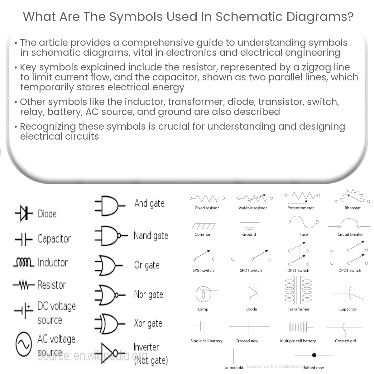
Schematic diagrams use symbols like resistors, capacitors, inductors, transformers, diodes, transistors, switches, relays, and power sources to represent circuits.
Understanding Symbols in Schematic Diagrams
Schematic diagrams are a fundamental tool in the world of electronics and electrical engineering. They provide a visual representation of an electrical circuit using standardized symbols, making it easier for engineers and technicians to understand and troubleshoot a circuit. In this article, we will explore some of the most common symbols used in schematic diagrams and their meanings.
Resistors and Capacitors
- Resistor: A resistor is represented by a zigzag line. It is used to limit the flow of current in a circuit and is measured in Ohms (Ω).
- Capacitor: A capacitor is shown by two parallel lines with a gap in between. It stores electrical energy temporarily and is measured in Farads (F).
Inductors and Transformers
- Inductor: An inductor symbol consists of a series of loops or coils. Inductors store energy in a magnetic field and are measured in Henrys (H).
- Transformer: Transformers are represented by two inductor symbols connected by a line. They transfer electrical energy between two or more circuits by electromagnetic induction.
Diodes and Transistors
- Diode: A diode is depicted as a triangle pointing in one direction with a vertical line at the tip. It allows current to flow in one direction while blocking it in the opposite direction.
- Transistor: A transistor symbol consists of three components: a circle, a vertical line, and horizontal lines connecting to the vertical line. Transistors are used to amplify or switch electronic signals and come in two types: NPN and PNP.
Switches and Relays
- Switch: A switch symbol looks like a break in a wire with a diagonal line connecting the two ends. It allows manual control of the flow of current in a circuit.
- Relay: A relay symbol consists of a rectangular coil with a switch connected to it. Relays are electrically-operated switches that use a small current to control a larger current.
Power Sources and Ground
- Battery: A battery symbol is made up of alternating long and short parallel lines. It represents a direct current (DC) power source.
- AC Source: An alternating current (AC) source is represented by a circle with a sine wave inside. It supplies power that changes direction periodically.
- Ground: The ground symbol is depicted as a series of horizontal lines, with each line shorter than the one above it. It represents a common reference point for the circuit.
These are just a few examples of the many symbols used in schematic diagrams. Familiarizing yourself with these symbols is essential for understanding and designing electrical circuits.


