30-second summary
How voltmeter works
An analog voltmeter uses an electromechanical mechanism that converts current flowing through the wire into a voltage reading. Digital voltmeters use a special type of analog-to-digital converter called an integrating converter.
A common analog voltmeter, for example, is likely to use an electromechanical mechanism that converts current flowing through the wire into a voltage reading.
An analog voltmeter usually contains a built-in, high-value fixed resistance, and an ammeter measuring the current passing through it. The current sensed by the ammeter is then converted to reading in volts.
Digital voltmeters are usually designed around a special type of analog-to-digital converter called an integrating converter.
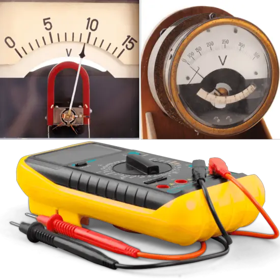

Voltmeters are instruments used for measuring the electric potential difference between two points in an electric circuit. To find the potential difference between any two points in the circuit, the voltmeter terminals are connected between those points without breaking or cutting the wire. Voltmeters are connected in parallel. They are made in a wide range of styles, some separately powered (e.g. by the battery), and others powered by the measured voltage source itself. Their functionality is usually built into modern multimeters.
An ideal voltmeter would have infinite resistance, so connecting it between two points in a circuit would not alter any of the currents. Real voltmeters always have finite resistance, but a voltmeter should have large enough resistance that connecting it to a circuit does not change the other currents appreciably. Voltmeters that can measure a potential difference of 1 μV are common, and sensitivities down to 10-12 can be attained. Digital meters can be made with high accuracy, typically better than 1%. Specially calibrated test instruments have higher accuracies.
How does a voltmeter work?
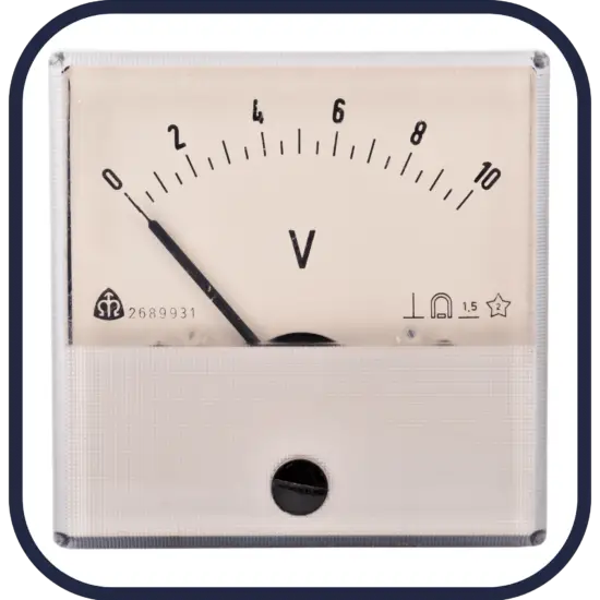
A common analog voltmeter, for example, is likely to use an electromechanical mechanism that converts current flowing through the wire into a voltage reading. An analog voltmeter usually contains a built-in, high-value fixed resistance, and an ammeter measuring the current passing through it. The current sensed by the ammeter is then converted to reading in volts. Its operation is based on Ohm’s law idea: “Voltage across a resistance is directly proportional to the current traveling through it,”.
Ohm’s law: V = I x R
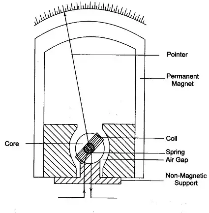
For example, the D’Arsonval meter or galvanometer works by deflecting a pointer in response to an electric current flowing through a coil in a constant magnetic field. A moving coil galvanometer can be used as a voltmeter by inserting a resistor in series with the instrument. The galvanometer has a coil of fine wire suspended in a strong magnetic field. When an electric current is applied, the interaction of the magnetic field of the coil and of the stationary magnet creates a torque, tending to make the coil rotate. The torque is proportional to the current through the coil. The coil rotates, compressing a spring that opposes the rotation. The deflection of the coil is thus proportional to the current, which in turn is proportional to the applied voltage, which is indicated by a pointer on a scale.
How digital voltmeter works
Digital voltmeters are voltmeters that display AC and DC voltage values and use discrete numbers instead of pointer deflection, they are preferred over analog voltmeters. DVMs are usually designed around a special type of analog-to-digital converter called an integrating converter. An integrating ADC is a type of analog-to-digital converter that converts an unknown input voltage into a digital representation through the use of an integrator.
