Explore the basics of Resistor-Inductor (RL) circuits, their types, characteristics, mathematical analysis, and applications.
Introduction to Resistor-Inductor (RL) Circuits
Resistor-Inductor, commonly known as RL Circuits, play a fundamental role in the world of electronics and electrical engineering. The RL circuit is a type of electric circuit that consists of a resistor (R), which is wired in series or parallel with an inductor (L).
The behavior of an RL circuit is governed by Ohm’s law, Kirchhoff’s laws, and the properties of inductance. The relationship between voltage and current in an RL circuit is described by a differential equation that results from applying these laws and principles.
Types of RL Circuits
- Series RL Circuit: In a series RL circuit, the resistor and inductor are connected in a single path for the current to flow. The total resistance and reactance in the circuit are the sum of individual resistances and reactances.
- Parallel RL Circuit: In a parallel RL circuit, the resistor and inductor are connected in separate paths for the current to flow. The total resistance and reactance in the circuit are found by using the formulas for resistors and inductors in parallel.
Characteristics of RL Circuits
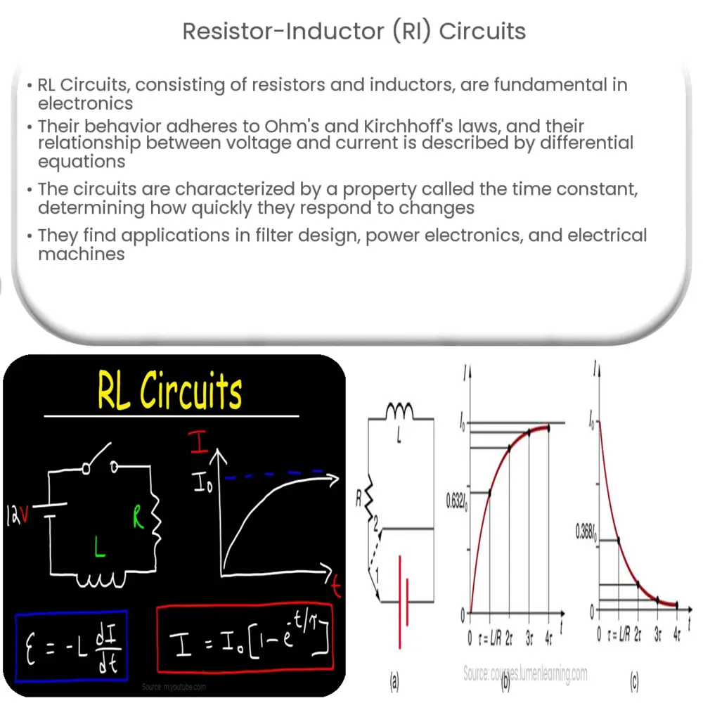
The behavior of RL circuits is characterized by a property known as time constant (τ), which is the time it takes for the current or voltage in the circuit to reach approximately 63.2% of its final value after a change in the circuit’s conditions. The time constant of an RL circuit is calculated by the formula τ = L/R, where L is the inductance and R is the resistance. Other important characteristics include phase difference, impedance, and resonant frequency.
During the ‘transient’ phase, when the circuit is still responding to a change, the inductor in the RL circuit resists changes in current, causing a delay before the current reaches its steady-state value. This phenomenon is often referred to as “inductive kickback”. Once the circuit reaches ‘steady state’, the inductor behaves as a short circuit, allowing full current to flow.
Next, we will look at the mathematical analysis of RL circuits, their applications, and how they behave under different conditions.
Mathematical Analysis of RL Circuits
Mathematical analysis of RL circuits involves using differential equations that come from applying Kirchhoff’s laws. For a series RL circuit, the differential equation is typically written in the form L(di/dt) + Ri = V, where V is the applied voltage, R is the resistance, L is the inductance, and i is the current. This equation describes how the current i changes over time as a result of the applied voltage and the properties of the resistor and inductor.
Applications of RL Circuits
- Filter Design: RL circuits are used in filter designs, where they help to pass or block certain frequencies in signal processing.
- Power Electronics: They are used in power electronics circuits for controlling the flow of power.
- Electrical Machines: RL circuits play a vital role in the working of electrical machines, including transformers and electric motors.
Behavior of RL Circuits Under Different Conditions
RL circuits behave differently under various conditions such as AC and DC supply:
- Under DC Conditions: In a DC RL circuit, once the transient period has passed, the inductor behaves as a short circuit. This is because the DC supply is constant and the inductor has reached its maximum magnetic field strength.
- Under AC Conditions: Under AC supply, the inductor’s reactance plays a significant role. The inductor’s reactance increases with the frequency of the supply, causing the current to lag behind the voltage.
Conclusion
In conclusion, RL circuits are fundamental to understanding the interaction between resistance and inductance in a circuit. They demonstrate important principles and find numerous applications in various fields. Understanding the mathematical formulation and the behavior of RL circuits under different conditions provides a robust foundation for further study and practical work in electrical and electronic engineering.
