30-second summary
Resistance
Resistance is the property of a material or component that opposes the flow of electric current through it. It is measured in Ohms and denoted by the symbol “Ω”.
Resistivity and resistance are related but distinct concepts in electrical circuits.
Resistance is a measure of how difficult it is for electrical current to flow through a material, and it is measured in ohms (Ω). The resistance of a material depends on its geometry (length, cross-sectional area, etc.) and its resistivity (ρ), which is a fundamental property of the material.
Materials can be classified into different categories based on their electrical resistivity. Here are some common categories:
Resistance
Resistance is the property of a material or component that opposes the flow of electric current through it. It is measured in Ohms and denoted by the symbol “Ω”.
Resistance arises due to the interactions between electrons and the atoms or molecules that make up the material. When an electric current flows through a material, the electrons collide with these atoms or molecules, causing the electrons to lose energy and reducing the flow of current.
The resistance of a material depends on several factors, including its length, cross-sectional area, and the material’s resistivity, which is a measure of how strongly the material opposes the flow of current. Some materials, such as metals, have low resistance and are good conductors of electricity, while other materials, such as rubber or glass, have high resistance and are insulators.
Resistivity and Resistance
Resistivity and resistance are related but distinct concepts in electrical circuits.
Resistance is a measure of how difficult it is for electrical current to flow through a material, and it is measured in ohms (Ω). The resistance of a material depends on its geometry (length, cross-sectional area, etc.) and its resistivity (ρ), which is a fundamental property of the material.
Resistivity (ρ) is the intrinsic property of a material that describes how much resistance it offers to the flow of electrical current, and it is measured in ohm-meters (Ω·m). Resistivity is a measure of the material’s ability to conduct electricity and is dependent on factors such as temperature, composition, impurities, and pressure.
The relationship between resistance (R), resistivity (ρ), and geometry (l, A) of a conductor is given by the following equation:
R = ρ (l/A)
where l is the length of the conductor and A is its cross-sectional area. This equation shows that the resistance of a conductor increases with length and decreases with increasing cross-sectional area, while the resistivity of the material remains constant.
In summary, resistance is a measure of how much a material resists electrical current, while resistivity is an intrinsic property of a material that describes its ability to conduct electricity.
Resistance and Conductance
Resistance and conductance are two related properties of a material that describe its ability to conduct electricity. Resistance is the property of a material that opposes the flow of electric current through it, while conductance is the property that allows electric current to flow easily through a material.
Resistance is measured in Ohms (Ω) and is the inverse of conductance, which is measured in Siemens (S). Conductance is the reciprocal of resistance, meaning that the conductance of a material is equal to 1 divided by its resistance.
In other words, a material with high resistance will have low conductance, while a material with low resistance will have high conductance. Materials with high conductance are good conductors of electricity, while materials with low conductance are poor conductors or insulators.
Conductance and resistance are related by Ohm’s Law, which states that the current flowing through a conductor is directly proportional to the voltage applied across it, and inversely proportional to its resistance. This means that if the voltage applied across a material is increased, the current flowing through it will also increase, assuming its resistance remains constant. Conversely, if the resistance of a material is increased, the current flowing through it will decrease, assuming the voltage applied across it remains constant.
Classification of Materials according to Electrical Resistivity
Materials can be classified into different categories based on their electrical resistivity. Here are some common categories:
- Conductors: Materials with low electrical resistivity, such as metals and some types of solutions, are known as conductors. They are able to carry an electric current with minimal resistance and are commonly used in electrical and electronic applications.
- Insulators: Materials with high electrical resistivity, such as plastics, rubber, and glass, are known as insulators. They are not able to carry an electric current easily and are commonly used to isolate and protect electrical components.
- Semiconductors: Materials that have intermediate levels of electrical resistivity, such as silicon and germanium, are known as semiconductors. They can be used to control and manipulate the flow of electric charge and are used extensively in electronics and computer applications.
- Superconductors: Materials that have zero electrical resistance at very low temperatures are known as superconductors. They are able to carry electric current without any loss of energy and are used in specialized applications such as MRI machines and particle accelerators.
Generally, most metals have high conductivity (which is another way of saying metals tend to be conductors) because the electrons in their outermost shell can move easily. Non-metals tend to have low conductivity.
Resistance of various devices
The resistance of electrical components can vary widely depending on their design, materials, and intended use. Here are ten examples of electrical components and their typical resistance values:
- Resistor: A component designed to have a specific resistance value. Resistance can range from a few ohms to several megaohms, depending on the specific application.
- Light bulb: Incandescent light bulbs have a filament that heats up and emits light when electricity flows through it. The resistance of a typical light bulb ranges from a few hundred to several thousand ohms.
- Diode: A semiconductor device that allows current to flow in only one direction. The resistance of a diode is relatively low in the forward direction (usually less than 1 ohm) and high in the reverse direction (several megaohms).
- Capacitor: A component that stores electric charge. The resistance of a capacitor is typically very high (several megaohms to gigaohms) and varies with frequency.
- Inductor: A component that stores energy in a magnetic field. The resistance of an inductor is typically low (a few ohms to a few hundred ohms) and varies with frequency.
- Transistor: A semiconductor device that can amplify or switch electrical signals. The resistance of a transistor can vary widely depending on the specific configuration and application.
The resistance of a material depends on several factors, including:
- Material properties: The type of material and its chemical composition can affect its resistance. For example, metals tend to have low resistance, while insulators have high resistance.
- Temperature: The resistance of most materials increases with temperature due to the increased atomic vibrations, which cause more collisions and reduce the flow of electrons.
- Length: The longer the material, the greater its resistance, as there is more material for the electrons to travel through.
- Cross-sectional area: The larger the cross-sectional area of the material, the lower its resistance, as there is more space for the electrons to flow through.
- Presence of impurities or defects: The presence of impurities or defects in a material can increase its resistance, as these can interfere with the flow of electrons.
- Frequency: In some materials, the resistance can vary with the frequency of the electrical signal passing through it.
- Mechanical stress: Some materials can change their resistance when subjected to mechanical stress or strain, due to changes in their shape or crystal structure.
Overall, the resistance of a material is a complex function of these factors and can be affected by other factors as well, depending on the specific material and application.
Resistance of various home devices
Here are five examples of resistance in ohms of various home devices:
- Incandescent light bulb: The resistance of an incandescent light bulb varies depending on its wattage and voltage. For example, a 60-watt bulb designed to work with a 120-volt power supply will have a resistance of approximately 240 ohms.
- Electric heater: An electric heater typically has a resistance ranging from 10 ohms to several hundred ohms, depending on its size and power rating. For example, a small 1,500-watt electric heater designed to operate on a 120-volt power supply will have a resistance of approximately 10 ohms.
- Electric stove: The heating elements in an electric stove typically have resistances ranging from 10 to 100 ohms, depending on their size and power rating. For example, a typical 8-inch burner on an electric stove may have a resistance of around 20 ohms.
- Electric iron: An electric iron typically has a resistance ranging from 10 to 30 ohms, depending on its size and power rating. For example, a typical 1,500-watt electric iron designed to operate on a 120-volt power supply will have a resistance of approximately 10 ohms.
- Electric toaster: The heating elements in an electric toaster typically have resistances ranging from 10 to 50 ohms, depending on their size and power rating. For example, a typical two-slice toaster may have heating elements with a combined resistance of around 20 ohms.
How to measure resistance
Resistance can be measured using a device called a multimeter, which is a tool used to measure electrical properties such as voltage, current, and resistance. Here are the steps to measure resistance using a multimeter:
- Turn off the power source: If the circuit being measured is powered, turn off the power source and disconnect any batteries.
- Set the multimeter to the resistance setting: Set the dial or switch on the multimeter to the resistance setting, usually denoted by the Greek letter omega (Ω).
- Connect the test leads: Connect the red test lead to the positive (or resistance) terminal on the multimeter and the black test lead to the negative (or common) terminal on the multimeter.
- Touch the test leads to the material being measured: Touch the two test leads together to verify that the multimeter is functioning correctly. Then, touch the test leads to the material being measured, making sure that they are in good contact with the material.
- Read the resistance: The multimeter will display the resistance measurement on its screen in Ohms (Ω).
It is important to note that when measuring resistance, the material being measured must be disconnected from any power source or other electrical components, and the probes of the multimeter should not touch each other while measuring resistance. Additionally, the multimeter should be set to the appropriate range for the resistance being measured to obtain an accurate measurement.
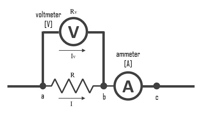
Ammeter–voltmeter method for measuring resistance
The ammeter-voltmeter method is a technique used to measure the resistance of an electrical component. It involves using an ammeter and a voltmeter in a circuit with the component whose resistance is to be measured. Here are the steps to follow:
- Disconnect the power source from the circuit.
- Connect the ammeter in series with the component whose resistance is to be measured.
- Connect the voltmeter in parallel with the component.
- Reconnect the power source to the circuit.
- Read the current on the ammeter and the voltage on the voltmeter.
- Use Ohm’s Law (R = V/I) to calculate the resistance of the component, where R is the resistance, V is the voltage across the component, and I is the current through the component.
Resistance and Joule heating
Ohm’s law can be explained at a microscopic level by understanding the behavior of electrons in a conductor.
In a conductor, such as a metal wire, there are free electrons that are able to move through the material. These electrons collide with the atoms of the conductor as they move, which creates a resistance to their motion. The resistance of a conductor is related to the number of collisions that occur as electrons move through it.
When a voltage is applied across a conductor, it creates an electric field that causes the free electrons to move in a particular direction. The electrons experience a force due to this electric field, which causes them to accelerate and move through the conductor. However, the electrons do not move in a straight line but rather undergo a random motion due to collisions with the atoms of the conductor, losing energy and scattering in random directions. This creates resistance to the flow of electrons and causes some of the energy of the electric field to be converted into heat.
Ohm’s law can be understood in terms of this electron behavior. The current through a conductor is directly proportional to the voltage applied across it, because a higher voltage creates a stronger electric field that causes the electrons to move faster, resulting in a higher current. However, the current is inversely proportional to the resistance of the conductor, because a higher resistance means that there are more collisions and, therefore fewer free electrons available to carry the current.
Joule heating is a phenomenon that occurs due to the resistance of the material, as the energy lost by the electrons is converted into heat. The amount of heat generated is proportional to the square of the current flowing through the material and the resistance of the material itself, as described by Joule’s Law.
Joule heating can be both useful and problematic. In some applications, such as electric heating elements or incandescent light bulbs, Joule heating is intentionally used to generate heat. However, in many other situations, such as in electronic circuits, Joule heating is considered wasteful and can cause overheating and damage to components.
To minimize the effects of Joule heating, it is important to use materials with low resistance and to design circuits that minimize the current flowing through high resistance components. Additionally, heat sinks or cooling mechanisms can be used to dissipate the heat generated by Joule heating.
Calculation of Joule Heating
Joule heating is the process by which electrical energy is converted into heat when an electrical current passes through a material with resistance. The amount of heat generated is proportional to the resistance of the material and the square of the current flowing through it, according to Joule’s Law. The formula for calculating Joule heating using resistance is:
Joule heating = I2 . R . t
Where: I = the current flowing through the material (in amperes, A) R = the resistance of the material (in ohms, Ω) t = the time the current flows through the material (in seconds, s)
To calculate the amount of Joule heating generated by a current flowing through a material with resistance, you would need to know the values of I, R, and t, and then use the formula above to determine the amount of heat generated. For example, if a current of 2 amps flows through a resistor with a resistance of 10 ohms for 5 seconds, the Joule heating generated would be:
Joule heating = 22 . 10 . 5 = 200 Joules
So, in this case, 200 Joules of heat would be generated by the electrical current passing through the resistor.
Resistance – Hydraulic Analogy
The hydraulic analogy, or the electric-fluid analogy, is a widely used analogy between hydraulics and electricity, which is a useful tool for teaching and for those who are struggling to understand how circuits work. it can also be applied to heat transfer problems.
Since electric current is invisible and the processes in play in electronics are often difficult to demonstrate, the various electronic components are represented by hydraulic equivalents. The relationship between voltage and current is defined (in ohmic devices like resistors) by Ohm’s law. Ohm’s Law is analogous to the Hagen–Poiseuille equation, as both are linear models relating flux and potential in their respective systems.
Electricity (as well as heat) was originally understood to be a kind of fluid, and the names of certain electric quantities (such as current) are derived from hydraulic equivalents.
- Voltage is like the pressure difference that pushes water through the hose. It is measured in volts (V). This model assumes that the water is flowing horizontally so that the force of gravity can be ignored.
- Current is equivalent to a hydraulic volume flow rate; that is, the volumetric quantity of flowing water over time. Usually measured in amperes. The wider pipe is, the more water will flow through. It is measured in amps (I or A).
- Resistance is like pipe diameter or obstacles in the hose that slow down the water flow. It is measured in ohms (Ω). In hydraulics, resistance is associated with the pressure loss coefficient.
- Resistors are comparable to a section of the pipe network where the radius of the pipe is constricted, restricting the rate of fluid flow in that region, the same way that a resistor limits current.
