A phase-locked loop (PLL) decoder is a control system that synchronizes output signal frequency and phase to a reference input signal, used in communication systems and digital electronics.
Phase-locked loop (PLL) Decoder: An Overview
Introduction
A phase-locked loop (PLL) is a control system that generates an output signal whose phase is related to the phase of an input signal. PLL decoders play a crucial role in a wide range of applications, including frequency synthesis, clock recovery, and data demodulation. This article aims to provide an overview of the PLL decoder, its components, and its applications.
Basic Components of a PLL Decoder
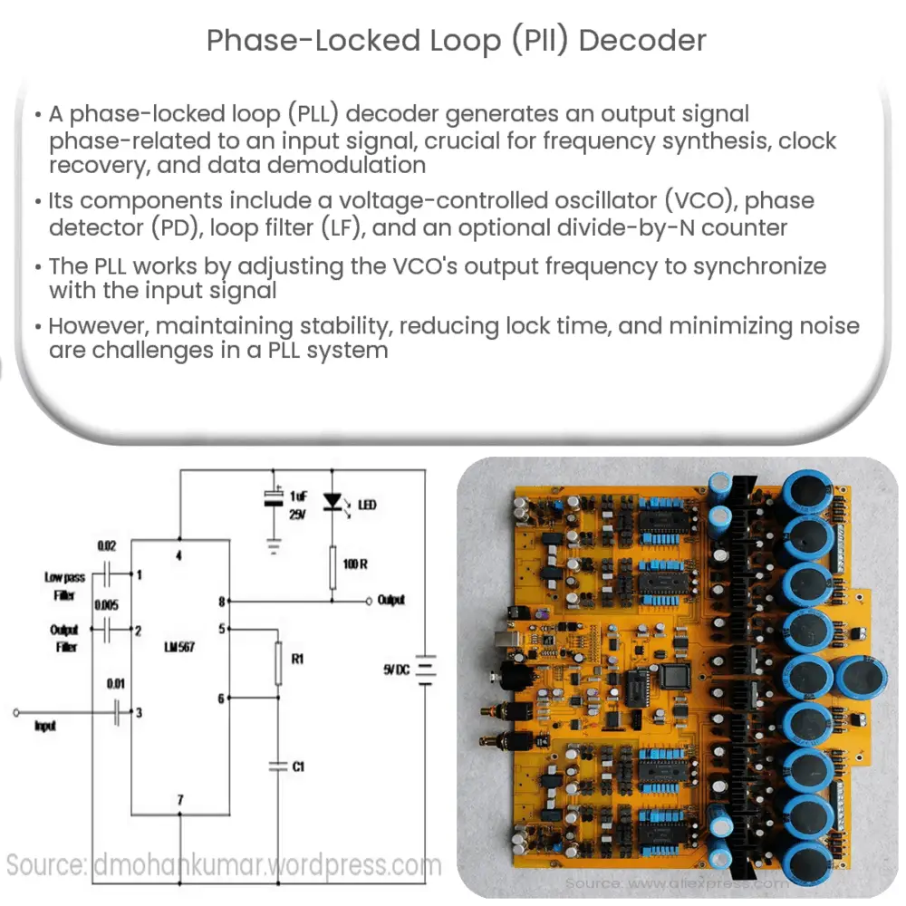
A PLL decoder consists of four essential components:
- Voltage-controlled oscillator (VCO)
- Phase detector (PD)
- Loop filter (LF)
- Divide-by-N counter
Voltage-Controlled Oscillator (VCO)
The voltage-controlled oscillator is a critical component of the PLL decoder, as it generates an output frequency that varies depending on the input control voltage. This frequency is typically proportional to the input voltage. The VCO’s output serves as the input for the phase detector.
Phase Detector (PD)
The phase detector compares the phase of the VCO output signal with the phase of the input reference signal. Based on this comparison, the PD generates an output voltage, which is proportional to the phase difference between the two signals. The output of the PD is fed into the loop filter.
Loop Filter (LF)
The loop filter is responsible for removing high-frequency components from the phase detector’s output signal, leaving a smoother control voltage for the VCO. This process reduces the noise in the output signal and helps maintain stability in the PLL system.
Divide-by-N Counter
The divide-by-N counter is an optional component in the PLL decoder system. Its purpose is to divide the VCO’s output frequency by a predetermined integer value (N), allowing the PLL to generate a wider range of output frequencies. This feature is particularly useful in frequency synthesis applications.
Working Principle of a PLL Decoder
The PLL decoder operates by continuously adjusting the VCO’s output frequency until it is synchronized with the input reference signal. This process involves a feedback loop in which the phase detector and loop filter play essential roles. The phase detector compares the phase of the input reference signal with the VCO’s output signal, generating a voltage proportional to the phase difference. The loop filter then smooths this voltage, providing a control voltage for the VCO. The VCO adjusts its output frequency according to the control voltage, eventually reaching a steady-state condition where the output frequency is locked to the input reference signal.
Applications of PLL Decoders
PLL decoders have a wide range of applications in various industries, including communication systems, control systems, and digital electronics. Some common applications include:
- Frequency synthesis: PLL decoders are used to generate stable, precise output frequencies from a reference signal. This feature is essential in communication systems, such as radio transmitters and receivers, where the output frequency must be adjusted to different channels.
- Clock recovery: In digital communication systems, PLL decoders help recover the clock signal from the received data stream. This process is crucial for synchronizing the transmitter and receiver, ensuring accurate data transmission and reception.
- Data demodulation: PLL decoders are used to decode modulated data in communication systems, such as frequency shift keying (FSK) and phase shift keying (PSK), by synchronizing the received signal with the carrier signal.
- Jitter reduction: PLL decoders can be used to reduce the jitter or phase noise in clock signals, resulting in improved performance in digital systems.
Challenges and Limitations
While PLL decoders offer many advantages, they also have some limitations and challenges:
- Stability: Maintaining stability in a PLL system can be challenging, especially when dealing with wide frequency ranges and rapid phase changes. The loop filter design plays a critical role in ensuring stability.
- Lock time: The time it takes for a PLL to lock onto the input reference signal can vary, depending on factors such as loop bandwidth and input frequency. Reducing lock time can improve system performance, but may also impact stability.
- Noise performance: Noise in the input reference signal, VCO, and phase detector can affect PLL performance. Proper design and filtering techniques are required to minimize noise and maintain high-quality output signals.
Conclusion
Phase-locked loop decoders are essential components in many modern electronic systems, enabling frequency synthesis, clock recovery, and data demodulation. By understanding the basic components, working principles, and applications of PLL decoders, engineers and designers can effectively harness their capabilities and address potential challenges. Despite certain limitations, PLL decoders continue to play a critical role in a wide range of industries, contributing to the ongoing advancement of communication and digital systems.
