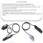
A multimeter measures voltage, current, and resistance by connecting probes to a circuit and selecting the appropriate setting on the device.
Introduction
A multimeter is a versatile instrument used by electricians and electronics enthusiasts to measure various electrical parameters, such as voltage, current, and resistance in a circuit. This article will provide a step-by-step guide on using a multimeter to measure these parameters.
Measuring Voltage
To measure voltage in a circuit, follow these steps:
- Turn the multimeter dial to the appropriate voltage setting (AC or DC).
- Insert the red probe into the voltage (V) input and the black probe into the common (COM) input.
- Connect the probes in parallel with the circuit element where you want to measure the voltage. The red probe should touch the positive (+) side, and the black probe should touch the negative (-) side.
- Read the voltage value displayed on the multimeter screen.
Measuring Current
To measure current in a circuit, follow these steps:
- Turn the multimeter dial to the appropriate current setting (AC or DC).
- Insert the red probe into the current (A) input and the black probe into the common (COM) input.
- Disconnect the circuit at the point where you want to measure the current, and connect the probes in series with the circuit. The red probe should touch the side connected to the positive (+) terminal, and the black probe should touch the side connected to the negative (-) terminal.
- Read the current value displayed on the multimeter screen.
Measuring Resistance
To measure resistance in a circuit, follow these steps:
- Turn the multimeter dial to the resistance (Ω) setting.
- Insert the red probe into the resistance (Ω) input and the black probe into the common (COM) input.
- Disconnect the circuit element you want to measure the resistance of, ensuring it is not connected to any voltage source.
- Touch the probes to the terminals of the circuit element, with the red probe on one side and the black probe on the other side.
- Read the resistance value displayed on the multimeter screen.
Conclusion
A multimeter is an invaluable tool for measuring electrical parameters in a circuit. By following the steps outlined in this article, you can accurately measure voltage, current, and resistance using a multimeter. Always remember to adhere to safety precautions and guidelines when working with electrical circuits.


