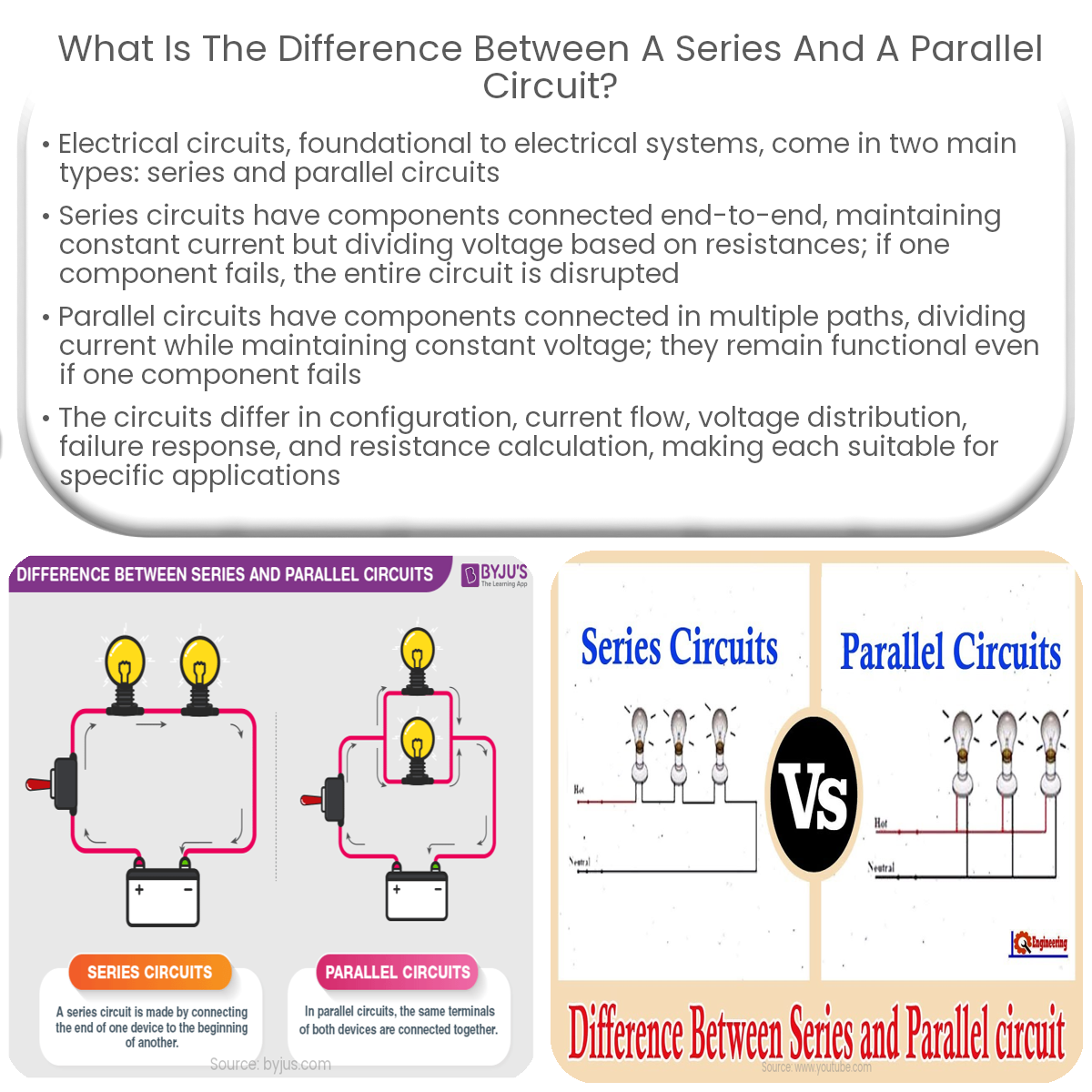
Series circuits have components in a single path with the same current, while parallel circuits have multiple paths, dividing the current among them.
Series and Parallel Circuits
Electrical circuits are the foundational structures of electrical systems, facilitating the flow of electric current through various components. Two main types of electrical circuits are series circuits and parallel circuits. Both serve unique purposes and exhibit distinct characteristics.
Series Circuits
In a series circuit, electrical components are connected end-to-end in a single path, allowing the current to flow through each component sequentially. The current remains the same throughout the circuit, but the voltage is divided among the components based on their resistances. A major characteristic of series circuits is that if one component fails or is disconnected, the entire circuit becomes nonfunctional, as the current flow is interrupted.
Parallel Circuits
Conversely, in a parallel circuit, components are connected in multiple paths, enabling the current to flow through more than one route. The voltage across each component remains the same, while the current is divided among the various paths according to their resistances. Unlike series circuits, if one component in a parallel circuit fails, the other paths continue to function, as the current can still flow through the remaining functional components.
Comparing Series and Parallel Circuits
- Current flow: In series circuits, the current is the same throughout, while in parallel circuits, the current is divided among the paths.
- Voltage distribution: Series circuits distribute voltage among the components, whereas parallel circuits maintain the same voltage across each component.
- Failure behavior: A failed component interrupts the current flow in a series circuit, rendering it nonfunctional, whereas parallel circuits continue to function even when a component fails.
- Resistance calculation: In series circuits, the total resistance is the sum of individual resistances, while in parallel circuits, the total resistance is calculated using the reciprocal formula: 1/Rtotal = 1/R1 + 1/R2 + …
In conclusion, series and parallel circuits differ in their configuration, current flow, voltage distribution, failure behavior, and resistance calculation. Each type of circuit is suited to specific applications, depending on the desired outcomes and functional requirements.