An op-amp integrator circuit performs mathematical integration of an input signal using an operational amplifier, resistor, and capacitor.
Introduction to Op-Amp Integrator Circuit
An operational amplifier (op-amp) integrator is an analog circuit that performs mathematical integration of an input signal. It is a fundamental building block in analog signal processing and control systems, used in applications such as filtering, waveform generation, and control systems.
Basic Op-Amp Integrator Circuit
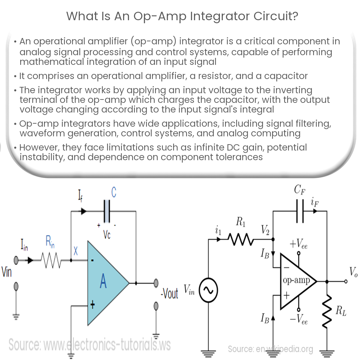
An op-amp integrator circuit consists of an operational amplifier, a capacitor, and a resistor. The input signal is applied to the inverting input terminal of the op-amp, while the non-inverting input is grounded. The resistor, R1, connects the input to the inverting terminal, and the capacitor, C, is connected between the inverting terminal and the output of the op-amp.
How Does an Op-Amp Integrator Work?
When an input voltage is applied to the inverting terminal through the resistor, R1, the op-amp maintains a virtual short circuit between its input terminals. This causes the current through R1 to charge the capacitor, C. As the capacitor accumulates charge over time, the output voltage changes according to the integral of the input signal.
The output voltage (Vout) is given by the equation:
Vout = – (1 / (R1 * C)) * ∫ Vin dt
Applications of Op-Amp Integrator Circuits
- Signal Filtering: Integrator circuits can act as low-pass filters, allowing only low-frequency signals to pass through while attenuating higher frequencies.
- Waveform Generation: Integrators are used in circuits to generate triangular and sine waveforms from square or pulse inputs.
- Control Systems: In control systems, integrators are used to implement integral control, which helps reduce steady-state errors and improve system performance.
- Analog Computing: Op-amp integrators can be used to solve differential equations, making them suitable for use in analog computers.
Limitations of Op-Amp Integrators
While op-amp integrators are versatile and useful, they have certain limitations:
- DC Gain: Op-amp integrators have infinite DC gain, which can cause the output to drift and saturate in response to small DC input signals or offsets.
- Stability: The phase shift introduced by the integrator can lead to instability in closed-loop systems if not properly compensated.
- Component Tolerances: The performance of an integrator circuit depends on the accuracy and stability of its resistor and capacitor components, which can affect the circuit’s time constant and response.