Different instruments for electric circuit analysis include voltmeters, ammeters, clamp meters, ohmmeters, LCR meters, impedance analyzers, oscilloscopes, signal generators, frequency counters, spectrum analyzers, wattmeters, and power analyzers.
Introduction
Electric circuit analysis is an essential part of electrical engineering and maintenance. It involves the study of electrical circuits to understand their behavior and performance. Test and measurement instruments play a crucial role in analyzing, designing, and troubleshooting electrical circuits. This article will provide an overview of the different types of test and measurement instruments used in electric circuit analysis.
Voltage and Current Measurement Instruments
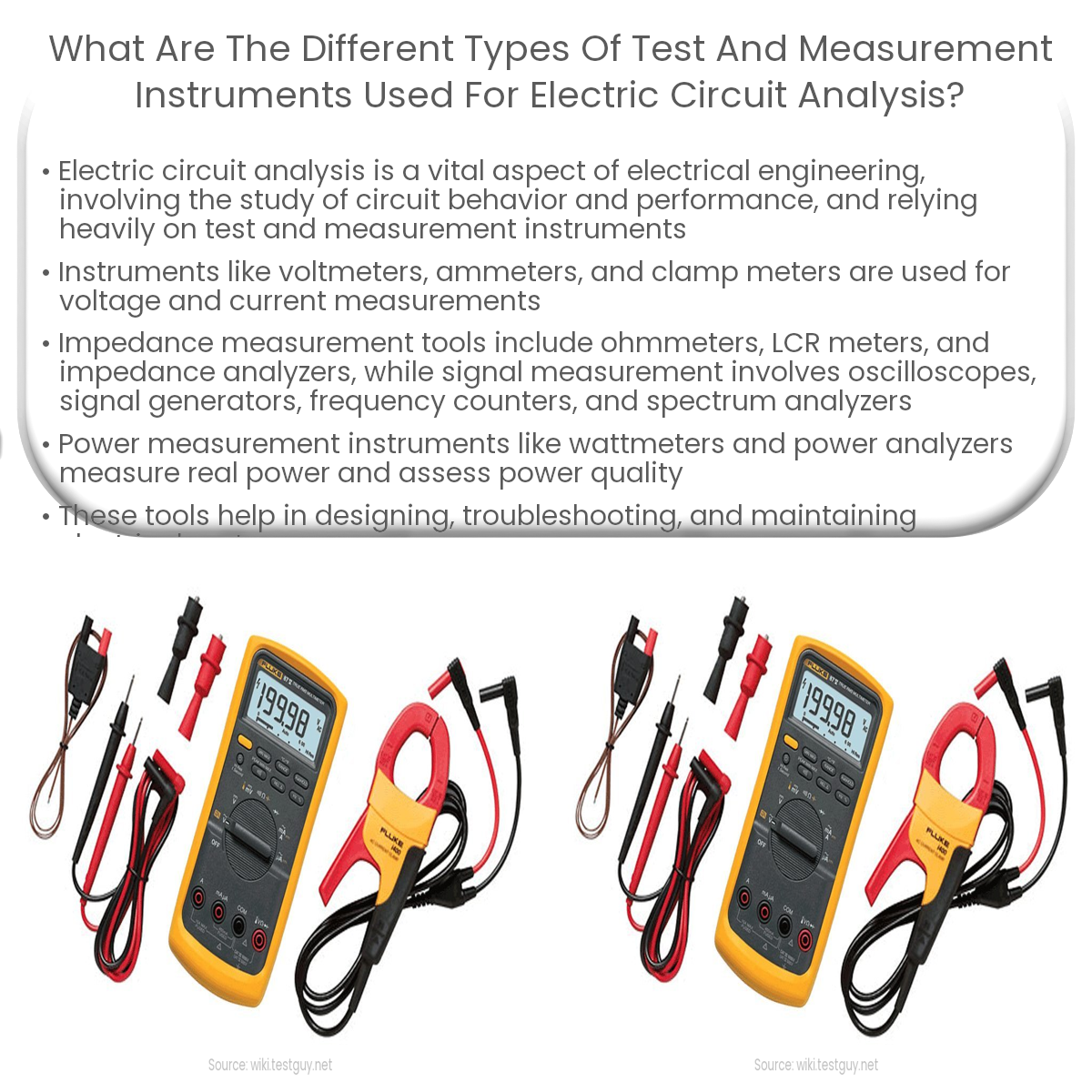
- Voltmeters: Voltmeters measure the voltage or potential difference between two points in a circuit. They are available in both analog and digital versions, with digital multimeters (DMMs) being the most common.
- Ammeters: Ammeters measure the current flowing through a particular segment of a circuit. They must be connected in series with the circuit to obtain accurate measurements.
- Clamp meters: Clamp meters are a non-invasive alternative to ammeters. They measure current by clamping around a conductor without needing to break the circuit.
Impedance Measurement Instruments
- Ohmmeters: Ohmmeters measure the resistance of a component or a segment of a circuit. They work by applying a known voltage across the component and measuring the resulting current.
- LCR meters: LCR meters measure the inductance (L), capacitance (C), and resistance (R) of a component. They are particularly useful for analyzing the impedance of passive components such as inductors and capacitors.
- Impedance analyzers: Impedance analyzers provide a more comprehensive analysis of a component’s impedance, including phase angle and frequency response.
Signal Measurement Instruments
- Oscilloscopes: Oscilloscopes capture and display electrical waveforms over time, allowing for the analysis of signal behavior, amplitude, frequency, and phase. They are essential tools for debugging and troubleshooting circuits.
- Signal generators: Signal generators produce various waveforms, such as sine, square, and triangular waves, with adjustable frequency and amplitude. They are used to stimulate circuits and test their response.
- Frequency counters: Frequency counters measure the frequency of an input signal by counting the number of cycles per unit of time.
- Spectrum analyzers: Spectrum analyzers display the frequency components of a signal, allowing for the identification and measurement of harmonic distortion and noise.
Power Measurement Instruments
- Wattmeters: Wattmeters measure the real power (in watts) consumed by a load in an AC circuit, taking into account both the voltage and current, as well as the power factor.
- Power analyzers: Power analyzers provide a more comprehensive assessment of power quality, including measurements of active, reactive, and apparent power, power factor, harmonics, and efficiency.
In conclusion, a variety of test and measurement instruments are used to analyze electric circuits, each with a specific purpose and functionality. By selecting the appropriate instruments, engineers and technicians can effectively design, troubleshoot, and maintain electrical systems.