Explore the fundamentals of vector-controlled induction motors, their working mechanism, implementation, and applications in various industries.
Understanding Vector-Controlled Induction Motors
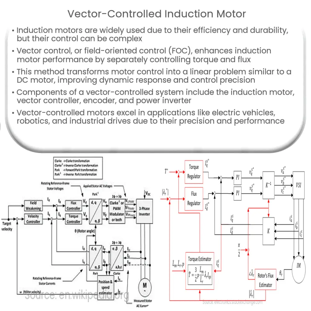
Induction motors, also known as asynchronous motors, play a pivotal role in various industrial and domestic applications. They owe their widespread use to their durability, efficiency, and relative simplicity. However, their control can be challenging due to the complex dynamic characteristics of these motors. One solution is the vector control, or field-oriented control (FOC), which significantly enhances the performance of induction motors.
Vector control, the subject of this discussion, is a method used to achieve better control over induction motors, enabling them to behave more like DC motors. It’s advantageous due to its capacity to separate the two primary variables affecting motor control: torque and flux.
The Principle of Vector Control
Vector control of induction motors works by decoupling the motor’s magnetic flux and torque, allowing each to be controlled independently. The principle is based on the creation of a rotating reference frame aligned with the rotor flux. Thus, motor control is transformed into a linear problem akin to a separately excited DC motor.
This method enhances the dynamic response of the motor, achieving better control over speed, torque, and position. The decoupling of torque and flux control also eliminates the mutual influence between them, yielding superior performance.
Components of Vector-Controlled Induction Motors
Vector-controlled induction motor systems typically comprise the following elements:
Each of these components is integral to the proper functioning of a vector-controlled induction motor system.
Working Mechanism
The working of a vector-controlled induction motor involves two axes: the direct axis (d-axis) associated with the motor’s magnetic flux, and the quadrature axis (q-axis) associated with the motor’s torque. The stator currents are controlled in such a way that they align with these axes, enabling independent control of flux and torque.
Implementation of Vector Control
Vector control is implemented through a feedback control loop which requires information about the rotor’s speed and position. This information is typically provided by an encoder. The vector controller uses this information to adjust the frequency and phase of the power inverter’s output. The result is a controlled voltage and frequency supplied to the induction motor, allowing precise control over torque and speed.
There are two types of vector control:
- Direct Vector Control: This method measures the rotor flux directly for feedback, thus requiring no mechanical sensors. However, it demands a more complex controller and a high-performance processor.
- Indirect Vector Control: This method estimates the rotor flux based on motor parameters such as stator voltage, current, and rotor speed. It’s simpler in comparison but requires accurate knowledge of the motor parameters.
Applications of Vector-Controlled Induction Motors
Vector-controlled induction motors find application in numerous areas where high performance and precision control are essential. Some notable applications include:
Conclusion
Vector-controlled induction motors are a significant advancement in motor control technology, offering superior performance, flexibility, and precision. By enabling independent control of torque and flux, they allow induction motors to match the performance of DC motors in various applications. Despite the complexity involved in their implementation, the benefits they offer, such as improved dynamic response and higher efficiency, make them a preferred choice in many industries. As technology continues to advance, we can expect further enhancements in vector control techniques, leading to even better performance and more widespread use of induction motors.
