Phasor diagrams help analyze AC circuits by visualizing the relationships between sinusoidal waveforms, like voltage, current, and impedance.
Using Phasor Diagrams to Analyze AC Circuits
Phasor diagrams are essential tools for understanding and analyzing the behavior of AC circuits. They allow engineers and students to visualize the relationships between sinusoidal waveforms, including voltage, current, and impedance.
Step 1: Convert Time Domain to Phasor Domain
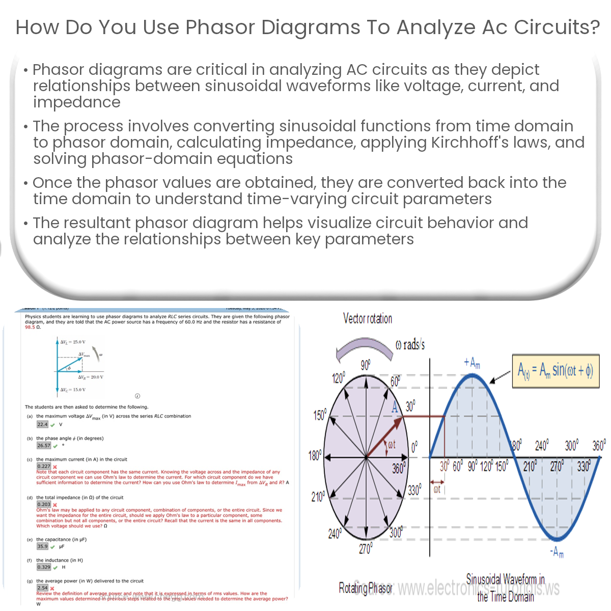
First, it is necessary to convert time-domain sinusoidal functions into the phasor domain. This involves transforming sinusoidal waveforms into complex numbers with magnitude and phase angle. For example, a sinusoidal voltage waveform V(t) = Vmsin(ωt + φ) can be represented as a complex phasor V = Vm∠φ.
Step 2: Calculate Impedance
Next, calculate the impedance of the circuit components. Impedance is a complex quantity that takes into account both resistance (R) and reactance (X). For inductors and capacitors, the reactance is given by:
- Inductive reactance (XL): XL = ωL
- Capacitive reactance (XC): XC = -1 / (ωC)
Then, the impedance (Z) can be calculated as Z = R + jX.
Step 3: Apply Kirchhoff’s Laws
Using the calculated impedances, apply Kirchhoff’s voltage and current laws to set up equations in the phasor domain. This will allow you to analyze the circuit and determine unknown currents, voltages, and impedances.
Step 4: Solve the Phasor Equations
Solve the phasor-domain equations using algebraic techniques, such as substitution or matrix methods. This will give you the phasor values for currents and voltages in the circuit.
Step 5: Convert Phasor Domain Back to Time Domain
Once you have the phasor values, convert them back into time-domain sinusoidal functions. This will give you the time-varying voltages and currents in the circuit.
Step 6: Visualize the Phasor Diagram
Finally, plot the phasor diagram by representing each phasor as a vector in the complex plane. The magnitude and phase angle of the phasors can be used to understand the behavior of the AC circuit and analyze the relationships between voltages, currents, and impedances.
In conclusion, phasor diagrams are a powerful tool for analyzing AC circuits, providing insight into the behavior and relationships between sinusoidal waveforms in a visually intuitive way.