To use a transistor as an amplifier, choose the right transistor, set up biasing, design input and output stages, and calculate the gain in your circuit.
Using a Transistor as an Amplifier in a Circuit
Transistors are versatile components in electronics, and one of their key applications is as amplifiers. In this article, we will discuss how to use a transistor as an amplifier in a circuit.
Understanding Transistor Configurations
There are three basic transistor configurations for amplification: common emitter, common base, and common collector. Each configuration has its advantages and disadvantages, but the most widely used is the common emitter configuration, which offers good voltage and current gain.
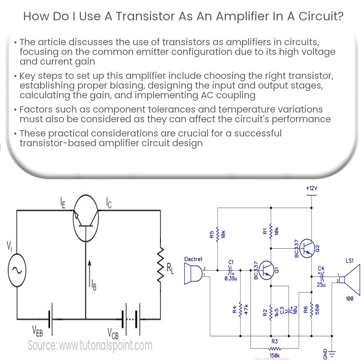
Common Emitter Amplifier Circuit
In a common emitter amplifier circuit, the emitter terminal is connected to a common reference point, usually ground. The input signal is applied to the base, while the output is taken from the collector. The following steps detail how to set up a common emitter amplifier circuit:
- Choose the right transistor: Select an appropriate transistor for the desired application. The transistor’s key specifications include the maximum collector current (IC), maximum collector-emitter voltage (VCE), and current gain (hFE).
- Set up the biasing: Proper biasing is essential to achieve linear amplification. Set up the base bias using a voltage divider network or a biasing resistor, ensuring that the transistor operates in its active region.
- Design the input stage: Connect a coupling capacitor between the input signal source and the base of the transistor. This capacitor blocks DC components and allows only AC signals to pass through, preventing the input signal from disturbing the biasing.
- Design the output stage: Place a load resistor (RL) between the collector and the supply voltage (VCC). This resistor determines the output voltage and current levels, as well as the circuit’s voltage gain.
- Calculate the gain: The voltage gain (Av) of the common emitter amplifier can be calculated using the following formula: Av = -hFE * (RL / (RL + RE)), where RE is the emitter resistor value.
- AC coupling: Use a coupling capacitor at the output to block DC and only allow the amplified AC signal to pass to the next stage or load.
By following these steps, you can successfully set up a transistor-based amplifier circuit. Keep in mind that practical considerations such as component tolerances and temperature variations may affect the circuit’s performance, so it’s essential to design with these factors in mind.